Bend Quality
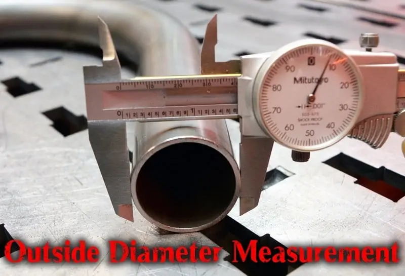
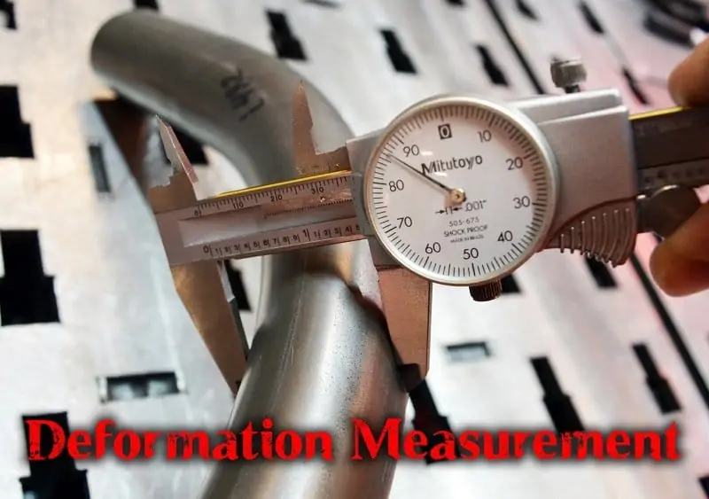
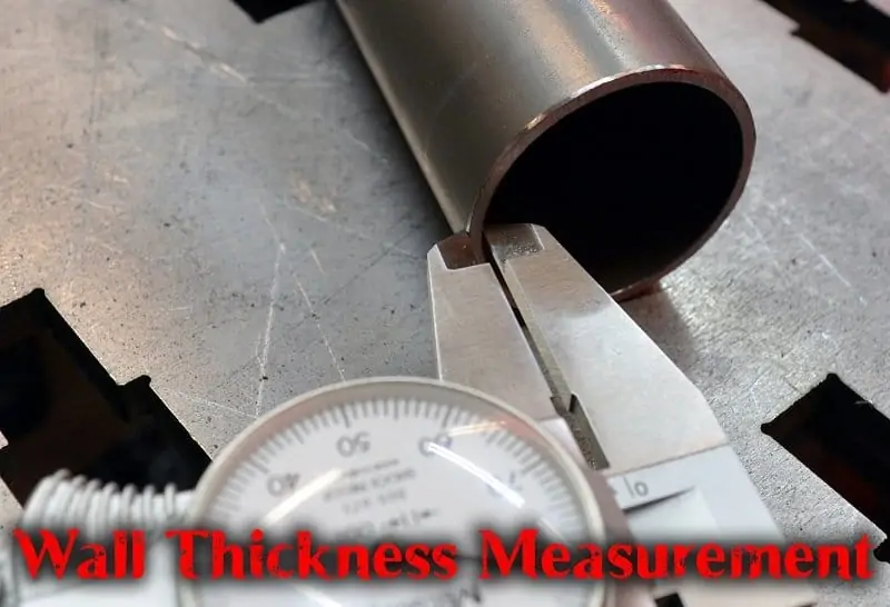
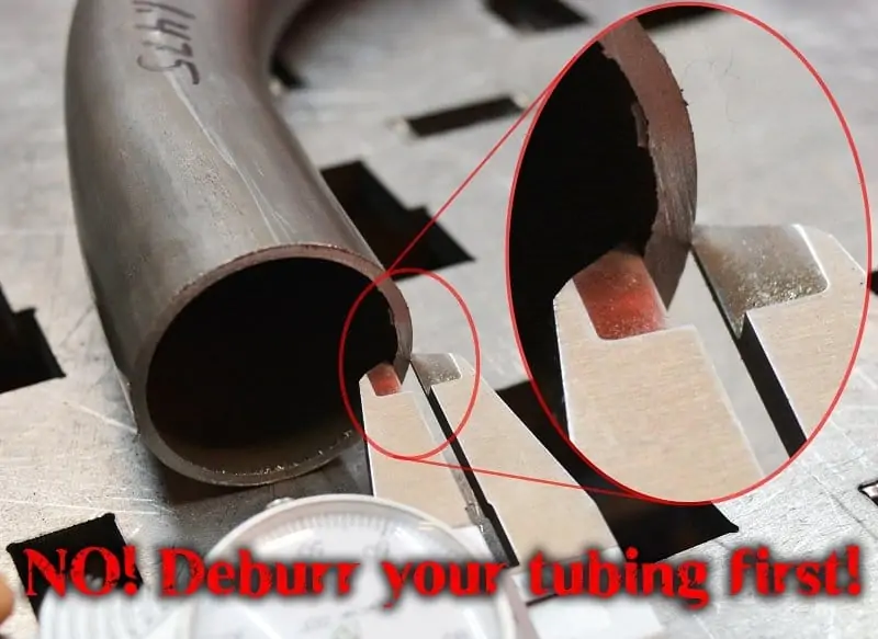
If you are using any tube/pipe bender and having issues with bend quality and deformation, you have come to the right place. We will help you learn how to measure and calculate your bend quality, and also how you can improve the bend quality you are getting on your M600 Mandrel Tubing Bender (standard or Mandrel). You will need calipers to perform these measurements.


Bend Quality Defects:
Wrinkles/Kinks
What causes them- D ratio too low, wall ratio too high, clamp block slipping, machine set up wrong.
Excessive Deformation
What causes it- D ratio too low, wall ratio too high, clamp block slipping, machine set up wrong.
Bump at Bend Start
What causes it- D ratio too low, wall ratio too high.
Material Cracks
What causes it- D ratio too low, wall ratio too high, or mandrel too far forward on mandrel applications. This is much more common on aluminum. Some materials are more prone to cracking, like aluminum. Some materials are more prone to wrinkling, such as copper and stainless steel. Materials that tend to bend well include Docol R8, 4130 Chromoly, Carbon steel, and Sandvik 2507 Duplex Stainless.
Solutions:
D Ratio Too Low
Since the D ratio is the bend radius (CLR) divided by the diameter of the tubing, increasing that ratio would require using a larger bend radius die or using smaller tubing. An alternative to changing bend radii or tube diameter is to use a mandrel to improve bend quality. Non-mandrel applications that produce bends in the 9-11.5% deformation range are EASY to get down to 2% or less deformation with a mandrel.
Wall Ratio Too High
Since the wall ratio of tubing is the diameter of the tubing divided by it’s wall thickness, decreasing that ratio would require using a higher wall thickness or using smaller tubing. An alternative to changing material (especially if you’re building a chassis from NHRA or SFI or other safety manual specifications) is to use a mandrel to improve bend quality. Non-mandrel applications that produce bends in the 9-11.5% deformation range are EASY to get down to 2% or less deformation with a mandrel.
Machine Set Up Wrong
Including full operation instructions here is not practical, but we will tell you the most common set up mistake made that affects bend quality is using a pressure die in the back of the machine (this hole is labeled “HD, never use on .120 wall or thinner”). If you are mandrel bending, the most common set up problem is mandrel position. Getting the perfect mandrel position will be the result of running several test bends with recordings of achieved bend quality and mandrel position used.
Clamp Block Slipping
The clamp block usually slides when it is clamped on dirty/oily material or If your material kinks/wrinkles. Kinks can cause the clamp block to slide when the material binds up in the machine. The clamp block slipping can also cause wrinkles, so it can be either a cause or a symptom. The solution is simple. If your clamp block has grooves/scratches from sliding, they must be removed. Recondition the surface with 220 grit sandpaper or emery cloth, rubbing the same way twisting the tube would rub the surface. Only a few light passes until the offending slip lines are gone (no more). Now clean it with lacquer thinner or acetone and a clean rag. Do not use any other cleaner. Clean your tubing at the clamp location the same way. We know this is extra work. Doing things right usually is. Now follow the clamping instructions, keeping bolt torque even. Remember that sliding oily tubing through your clamp blocks not only scratches them but fills in those scratches with oil. Clamp blocks are extremely affordable, so keep that in mind for spares and/or replacements. We have not yet seen an application (even with the added drag from a mandrel) where one clean clamp did not have enough clamping force other than our 1.5″ SQUARE tubing die, which we sell with two minimum clamp blocks.
Bend Quality Examples:
What Looks “Good”?
We have been to shows and talked to thousands of customers with bends to discuss. Most average fabricators consider 5% and less deformation to look excellent. Between 5% and 7% looks good to most people, but when asked if they can spot the deformation, they can usually see it. Between 7% and 9% is noticeably deformed, but usually acceptable on thinner wall ratios and tighter D dies. Between 9% and 11% is very noticeably deformed and looks bad to most people. There are only a few applications that cause this much deformation. See last paragraph in this section for more details, especially pertaining to comparing bends between manufacturers of tubing benders. All deformation averages are for carbon steels.
3% and less Deformation:
This is reserved for mandrel benders (ours included). Usually just 1 wall thickness above the minimum rated for a die on our mandrel bender will easily produce bends with well under 3% deformation. Nearly no person can see this deformation with their eyes.
5% – 7% Deformation:
7% – 9% Deformation:
9% – 11% Deformation:
Common Applications and Average Deformation:
1.00 x .120 on a 3.5/4.5 CLR – Usually below 5%
1.25 x .120 on 4.5 CLR – usually below 5%
1.50 x .120 on 4.5 CLR – 6%
1.50 x .083 on 6.0 CLR – 7%
1.625 x .095 on 6.0 CLR – 7%
1.625 x .083 on 6.0 CLR – 10.5%
1.625 x .083 on 4.5 or 6.0 CLR w/Mandrel- 2.5%
1.75 x .120 on 4.5 CLR – 10%
1.75 x .120 on 6.0 CLR – 7%
1.75 x .095 on 6.0 CLR – 10%
1.75 x .095 on 4.5 or 6.0 CLR w/Mandrel- 2.5%
2.00 x .120 on 6.0 CLR – 10.5%
2.00 x .120 on 4.5 or 6.0 CLR w/Mandrel- 1.0%
If you are bending for paying customers, the best thing to do is keep sample bends of each material/CLR you bend (or a similar completed project/build). Show them to your customers who bring up bend quality before they put a deposit on fabrication work. This eliminates surprises. To open up the door for higher revenue, buy one mandrel bend from us in 1.625x.083 4130 or another material you use, and keep that bend in your shop for sales purposes. When relevant, show the mandrel and non-mandrel bends and explain that the mandrel bends are more expensive to produce. If you get a deposit on that level of work, order your mandrel conversion for your Rogue Fab M600 and enjoy the new capacity.
My buddy’s bends look WAY better, what gives?:
Most of the tubing bender companies we compete with will not discuss/estimate bend quality with their customers. We don’t like our customers to be surprised, which is why this page exists.