Bending 101
This is currently being updated to add new offsets for the M601/605/625. Please let us know if you have any questions.
This is our page where you can learn how to bend tubing accurately with your new model 600, or any other tubing and pipe bender. Just like real college, we show you the old school way to do it and some theory before telling you about the software that can help do it all for you. But you can skip right to the end if you want to, we sell the best bending software there is, and it is quite affordable.
Bending Tube with a Rogue Model 600 Bender, 101: The basics
In bending 101, you will learn how to put a bend where you want it, based on where the bend starts, and how to bend the right amount. The Rogue Fabrication bender has a fixed bend offset for every radius of die. The bend offset is the distance between the start of the bend and where you line up the tube in the machine. See the image below.
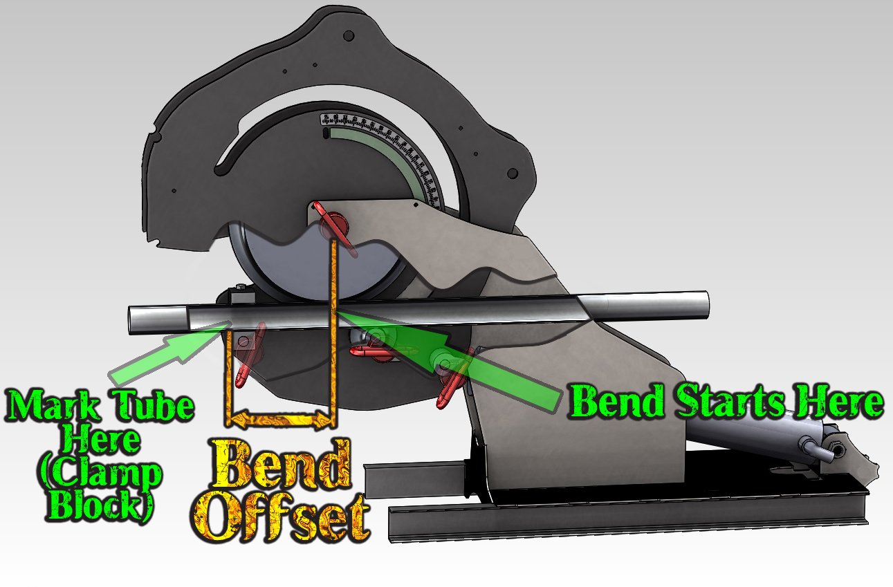
If you want to make a bend on a 4.5 radius die, and you want that bend to be 10 inches from the end of a piece of tube, mark a line on the tube 10 inches from the end. Your BEND STARTS HERE. Now draw a line that is 5 1/4″ closer to the end of the tube from your first line (5 1/4 is the bend offset from the table below). This line you just drew is where you line up the tube with the clamp block in the machine (“MARK TUBE HERE” in above image). The bend will start at exactly 10 inches from the end of the tube. Putting bends where you want them accurately is the foundation of accurate tube work.
If you don’t like bend offsets (like if you’re used to another machine), just buy one of our bend location gauges (click HERE – new window), it allows you to tape measure from bend start to any place on the tubing you want. No problem.
M600 Bend Offsets (2010-2014)
- 3.5″ CLR Dies – Offset 6 3/16″
- 4.5″ CLR Dies – Offset 5″
- 6.0″ CLR Dies – Offset 6 5/8″
M600 Bend Offsets (2015 to late 2021)
- 2.5″ CLR Dies – Offset 7 1/8″
- 3.5″ CLR Dies – Offset 6 1/4″
- 4.5″ CLR Dies – Offset 5 1/4″
- 6.0″ CLR Dies – Offset 6″
M601/605/625 Bend Offsets (Current)
- 2.5″ CLR Dies – Offset 4″
- 3.5″ CLR Dies – Offset 4 1/2″
- 4.5″ CLR Dies – Offset 5 1/4″
- 6.0″ CLR Dies – Offset 6″
What About Springback?
Here is the best way to measure your springback- Put straight material in the machine and hand pump the ram until it is just barely tight but not bending yet. Zero the degree indicator. If you want to bend a 90, bend EXACTLY 90, and then release ram pressure until the material is loose in the machine. Tighten the valve, and hand pump the ram until it is just barely tight on the material. Read your degrees, we’ll say for example that you read the degrees at 86.5. Now overbend by the difference. So you bend to 90, snug the machine up, read 86.5, then bend to 93.5 and pull out the tube and you will be at EXACTLY 90 after springback. Now you can overbend every 90 on that material by 3.5 degrees and they will all be spot-on! Springback is different for every material.
Bending 102
In bending 102, you will learn how to calculate the length of tubing in a bend, and also how to put a bend in the middle of a length of tube.
How Much Tubing is in a Bend?
Calculating the tubing in a bend is very simple. We already did the calculations for you. Just multiply the degrees you’re bending by the numbers below and you will get the length of tube in the bend. So if you’re bending 90 degrees on a 6″ CLR die, your tubing in the bend is 90 * .104, which equals 9.36 inches. Now you can add the bend length to your straight tube lengths and know your actual total cut length for your tubing!
- 6.0 CLR = .105″ of tube per degree of bend
- 4.5 CLR = .078″ of tube per degree of bend
- 3.5 CLR = .061″ of tube per degree of bend
- 2.5 CLR = .043″ of tube per degree of bend
Putting a Bend in the Middle of a Tube
Now that you know how to calculate the length of a bend, and where a bend will start based on where you clamp it in the machine, you can easily put a bend in the middle of a piece of tubing. Lets say you have a tube that is 45 inches long, and you want a 60 degree bend (done on a 1.75×6 CLR die) right in the middle of it. Draw a line in the middle of the tube. Your bend will be .104″ long per degree, so that is .104*60= 6.24″. So draw 2 more lines, each 3.12″ from the centerline. This is where the bends will end. Now we just add the bend offset (5 7/8″ in the table from bending 101), and put a line 5 7/8″ from one of the lines that you drew to mark the end of the bend. When you load the material in the machine, line up the last line you drew with the face of the clamp block closest to you, and make your bend. If you can’t see your centerline mark, it’s loaded into the machine the correct way. It’s that easy.
Is this too much work? No problem. We have a free calculator to help. Click HERE (opens in a new window/tab).
Watch a Project from Start To Finish
We have several videos of how to bend tubing for projects like roll cages and hand railings. These are start to finish narrated projects that go over measurement, avoiding mistakes, bending, notching, welding, and more!
Bending 103
In previous lessons, we showed you the basics for getting bend spacing and length figured out. Now we are going to show you some more advanced layout and bend spacing tips. Understanding this section will greatly improve your ability to plan and design bent parts that you can actually make in your tubing bender (which is obvisouly something you want to do!).
Close Together Coplanar Bends
Bends can be put much closer together than what you learned in bending 101. We will show you how. Two bends that are in line with each other are “Coplanar”. Another way to think about it is if you can lay the part flat on the ground when you’re done bending, all the bends are in the same plane, so they are coplanar.
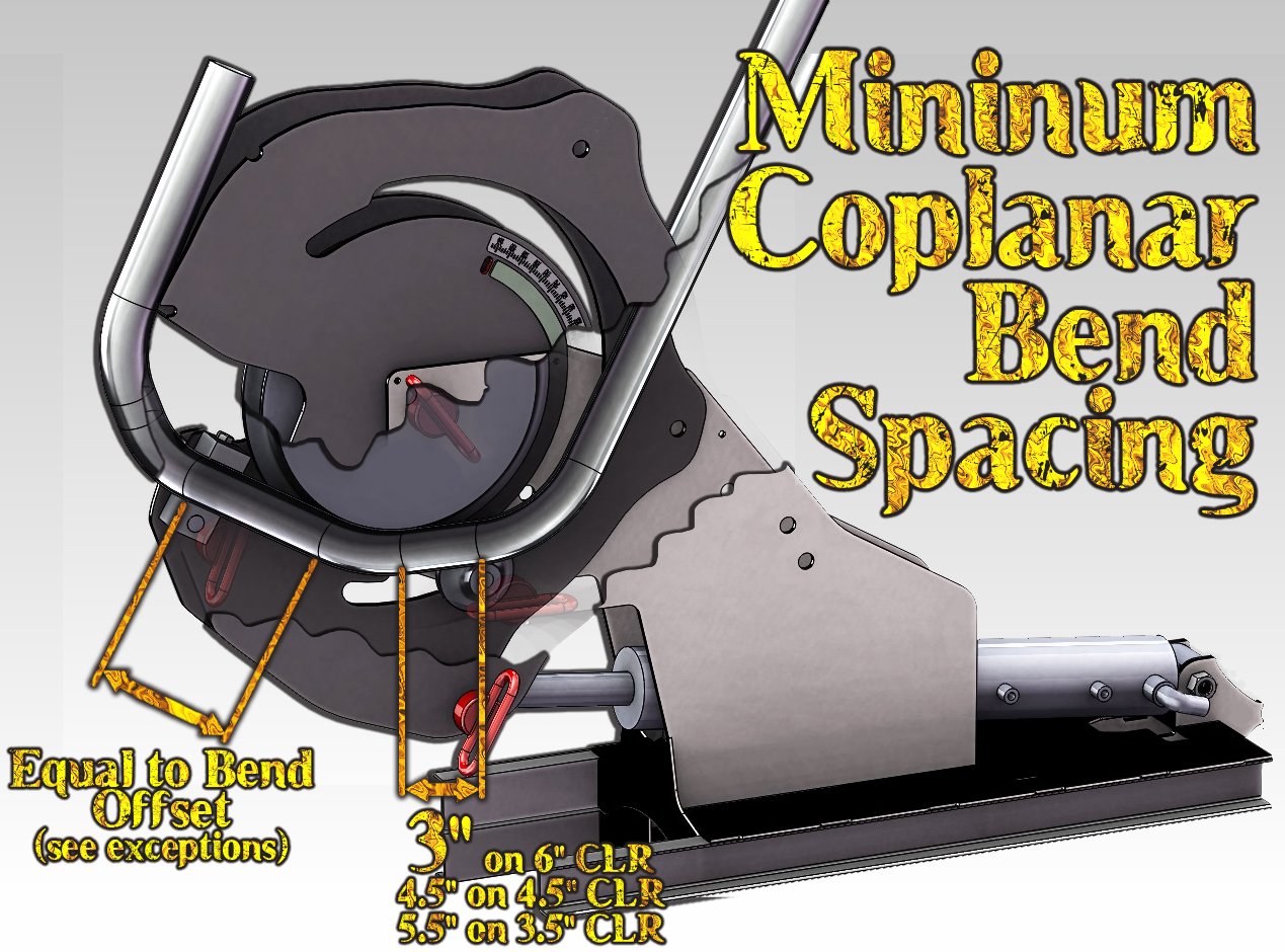
Three limits for bend spacing
- As explained in bending 101, you can always make a bend, put the clamp block after that bend, and have the bends spaced as close together as your bend offset allows. That is the dimension to the left in the above image. This method is simple, and doesn’t allow bends to be very close. It does allow any rotation between bends very easily though.
- As the image shows, you can put bends VERY close if you have a roller pressure die in the machine (the little wheel below the tube). Larger bend radii require more spacing here.
- You can also clamp right on a bend. This may require you to flip your clamp block (bolts on the block will now face down). You can use any pressure die pin location to engage the clamp block. Please note that once you clamp on a bend or flip the clamp block (or both), your bend offset will not match what is published. This is when our bend gauge becomes very useful (link HERE – opens in new window/tab). Doing this allows for true zero spacing bends – meaning there is no measurable length of tubing between two bends. The M600 is the only tubing bender in the world that we know of that is capable of doing this without tremendously expensive custom clamping dies being manufactured.
For an application example of zero spacing bends, read on. We have examples in bending 301 and also in bending 302.
Bending 201
So far we have only shown you how to make symmetrical parts, built the easy way (from the middle to the outside). In 201, we’re going to graduate to showing how to put bends closer together (by changing the order you make the bends in) and how to bend a non-symmetrical tube structure. We will show you how to make it from the middle to the outside, and also from one end to the other, including all the calculations. You do not need to understand this to bend tube successfully, so don’t worry if you don’t pick this up before you buy your first tubing bender! It will be easier to learn once you have done a few easier projects.
Non-Symmetrical Parts – A Little More Complex
- Draw your layout full size with sharp corners and dimension it (you can draw it on concrete, cardboard, paper, etc).
- Trace the bends accurately into the corners with the correct radius. Mark the beginning and end (optional) of the bends.
- Put a mark on your layout in the center of the tube. This is where we will start fabricating from.
- Move from the center of your layout to the right, draw a line 5” from the beginning of every bend (5″ is one of the bend offsets from the table in the 101 section, use the offset that matches your die and machine). Label these lines “clamp block”. Repeat this process to the left. What you will now have is the locations where you clamp the material in the machine to put the bends where they are in the layout.
NOTE – This layout is shown with some outdated bend offsets. The process is good, but the numbers are not longer correct for just the bend offsets. Please be patient as we update content. This will eventually be replaced.
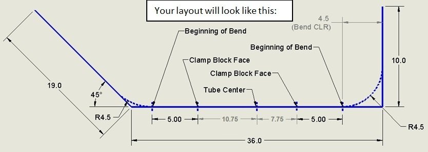
5. Now cut your tube to length, and put a mark in the very center of your tube. The length is simply all the straight lengths from the layout added up, plus the “take up” A.K.A. bend length which can be easily calculated using the numbers given in the 102 section above.
6. Measure out from center and draw your clamp block lines on the tube (7.75” and 10.75” in the example above).
7. Grab the tube centerline. Load into the bender (from front) until the clamp block line is on the front face of the clamp block.
8. Make your bend per machine instructions.
9. Remove the tube and lay it on top of your layout. You will be able to see any error. Now is the time to account for any stretching that may take place. If your second clamp block location doesn’t seem to be as close to the bend as you drew it, you may draw it closer and maintain as much accuracy as possible.
10. Repeat this process until you are done bending your layout. If you cut your tube to the full “sharp corner” length, You will have to cut the ends after you are done. Doing that would result in you having a longer cut length. This may be okay if you want to keep things simple and don’t mind a little waste.
Starting From One End of the Tube, Not the Middle
The following paragraph is a VERY DENSE explanation of another way to bend the same shape drawn above in Bending 103.
We’re going to bend from one end to the other, starting with the 90 degree bend (following the same layout from the 201 section). We want a 10 inch leg with a 4.5” bend, so we need 5.5” of straight tube (5.5″ tube, 4.5″ in the bend since it’s a 4.5 CLR die). Our offset is 5” (use the correct number for your machine from the table in the 101 section) for a 2015 to current machine for a 4.5” CLR die, so hang 0.5” of tube out of the end of the clamp block and bend 90 degrees. The bend length from the table is .078 per degree, So for our 90 that is .078*90=7.02 inches. It is another 28.5 inches from the end of the first 90 to the beginning of the next bend (add up the dimensions in the drawing). We can put the clamp block 28.5-5 inches from the end of our first bend, or we could have drawn a line on the tube before we started that was 5.5+7.02+28.5-5 inches from the starting end of the tube and used that as a clamp block location for bend 2. Clamp on the second line and bend, and you’re done. Don’t forget about springback.
Watch a Non-Symmetrical Project From Start To Finish
The owner shot this video while making the very first hand railing he has ever built. A little knowledge of how this easy to use tubing bender works and how tubing is laid out is all that was required to design and build the whole project without any waste. See how to make a multi-thousand dollar stainless steel hand railing for a few hundred dollars in material with nearly ZERO CALCULATIONS or math!
Bending 202
Just like in college, you’re forced to learn the theory before you get the real tools and find out “you’re never going to use the math”. While that quote isn’t always true, we’re going to show you the tools the pros use when they design roll cages, bend exhaust pipes, and other parts for their customer’s projects.
Advanced Tools for Accuracy – Software
Bend Tech makes several levels of software to help you run the design and manufacturing side of your business or get your project completed. We sell all of these in our store, just click on the icon for any software and you will be taken to the listing for that software.

Bend-Tech SE
Price: $599
Our SE (standard edition) commercial software for tube & pipe design/ manufacturing. If tube bending is part of your company’s business or you are serious about tube bending, then Bend-Tech SE is where you want to start. The big deal: Export to CAD systems!

Bend-Tech PRO
Price: $295
If you are designing chassis, roll cages, rock sliders, frames or anything from single parts to multiple tubing assembly then Bend-Tech PRO is where you want to start. The big deal – full assemblies and notching.

Bend-Tech EZ3D
Price: $149
If you need a few single parts bent with rotation, EZ3D is a start. EZ3D is also useful if you won’t be fabricating multiple tube assemblies such as roll cages, bumpers, etc. The big deal – 3D parts made accurately.

Bend-Tech EZ
Price: $69
If you are planning to bend just a few parts in a year and the parts are 2D single parts, then EZ may do the trick.
Why Use Software?
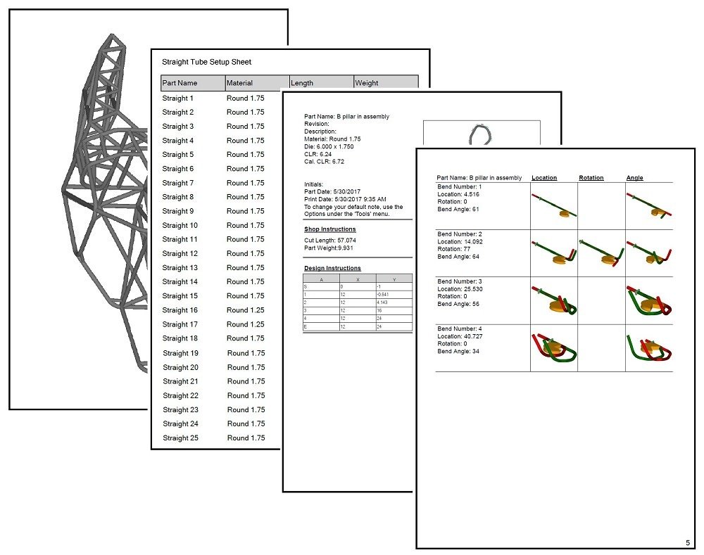
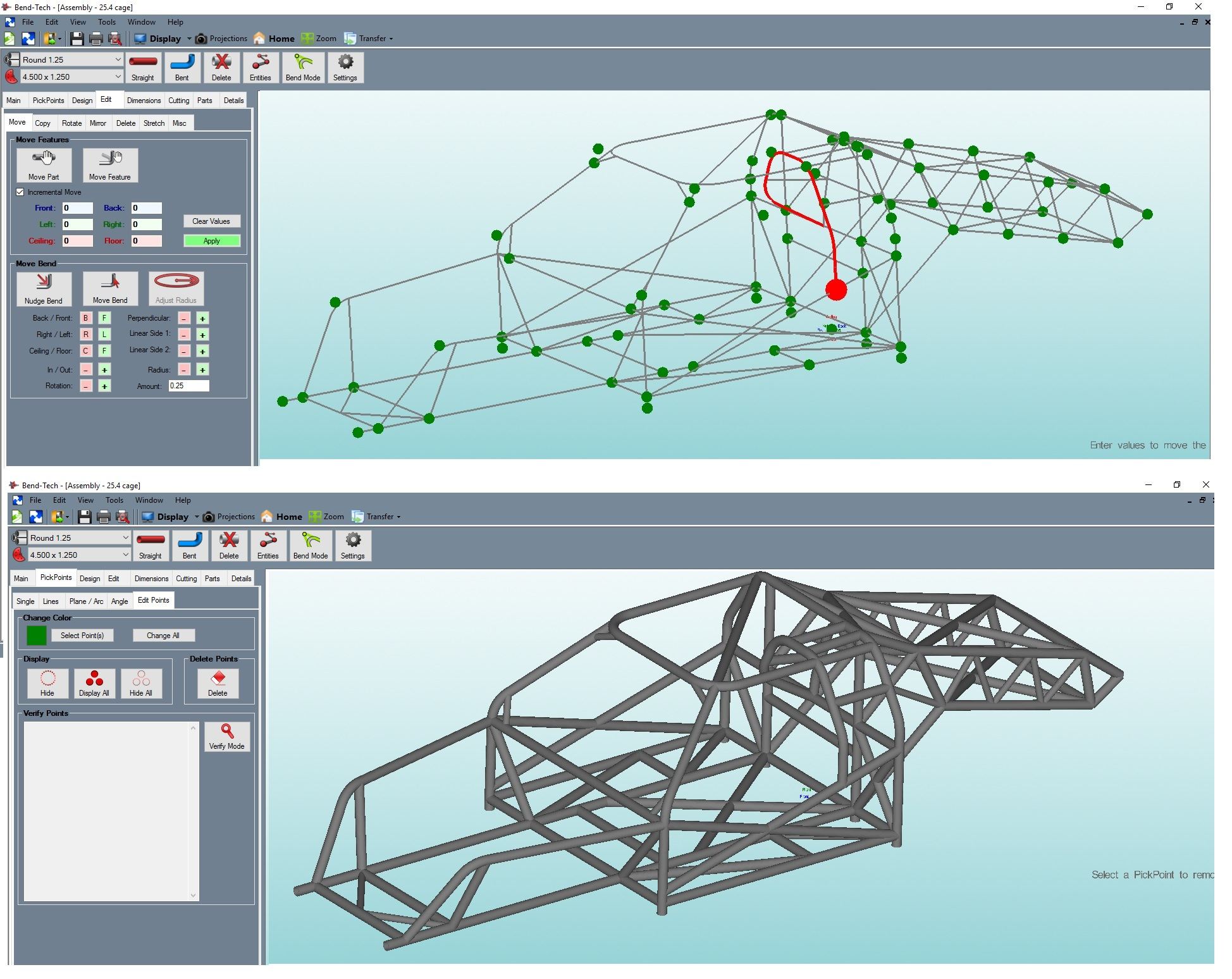
You can draw tube by hand or in SolidWorks or other CAD software, but none of them will generate manufacturing instructions. Bend Tech will print you a sheet of paper for every part with how long to cut it, what material to use, where to put the clamp block to get bend locations correct, and how many degrees to bend (including compensating for springback). Furthermore, PRO and SE will print cutting wrappers to help you with tube notching, and will generate sheet metal panels from just clicking on the tubes you want to make panels to fit. There are seriously too many useful features to describe in one little paragraph. You can adjust bend order on parts, scale parts, scale assemblies, etc.
Who Can Learn Bend Tech?
If you can use most computer programs with training, you should have no problem running this software. It is not “MS-Paint intuitive”… So don’t think you will be up and designing your chassis in 5 minutes. This is more like MS Excel. Go online and watch a video or read about a function and it will tell you where that button is and what it does. Watch the 30 or 40 minutes of videos on Bend Tech 7.x PRO and you can easily learn to design 3D parts, put them in an assembly, move them, edit them, print instructions, make more parts off that seed part, and use parts to cut each other to make perfect tube junctions.
Software Integration with the M600
Fire up Bend Tech and chose the M600 and dies in the die library, they come pre-loaded. Add your material to the database (like 1.75″ diameter .120″ wall tube), and click on “calibrate die”. Bend Tech will tell you to cut a chunk of tube and tell it the exact length. Then bend a 90 degree bend anywhere in the tube. Tell bend tech where the clamp block is from one end. Then set your “L” on the table and measure the height with a tape measure. Flip it and measure the length of the bottom of the “L”. Put those two lengths in Bend Tech and it will calculate the amount of of stretch per degree on that tubing, the effective CLR (a 6 inch radius die bends bigger than a 6 inch radius with material elasticity), and use these values EVERY time you select that material and die. Now bend tech will actually use the calibrated values to determine more accurate bend locations, and exact bend lengths to make your designs accurate down to the fractions of inches that your tubing stretches when it is bent.
And Spring back? Easy! Bend any 2 amounts and tell bend tech the springback amount, and it will interpolate the entire bending range to tiny fractions of a degree. So you bend a 35 degree bend (on the degree indicator), back the machine off and advance it until the pins are snug to read springback (see above in bending 102 for more info on springback), and you get a 32 degree net, so 35-32 is 3 degrees of springback. Tell bend tech you lost 3 degrees on a 35 degree bend. Now do it again at some bigger number, like 100. Tell bend tech the springback, like 5 degrees for example. Bend tech will use these two points to calculate the entire range of possible springback values and you call tell the software to take them into account (by checking a box) when you print your part manufacturing instructions. So it will say “bend angle 38 degrees” when your design is for 35, so it comes out correct. No more bending twice to compensate/measure for springback!
Bending 301
Bending 101 through 202 are meant to equip you with the know-how to tackle most simple projects with some practice. In our 300 level content, our goal is to help you learn to do complex beand features that you can integrate into your already strong foundation of knowledge.
How to do S – Bends, Method 1
1. If a picture is worth 1000 words, how many is a video worth? Don’t answer. Just watch the video.
How to do S – Bends, Method 2
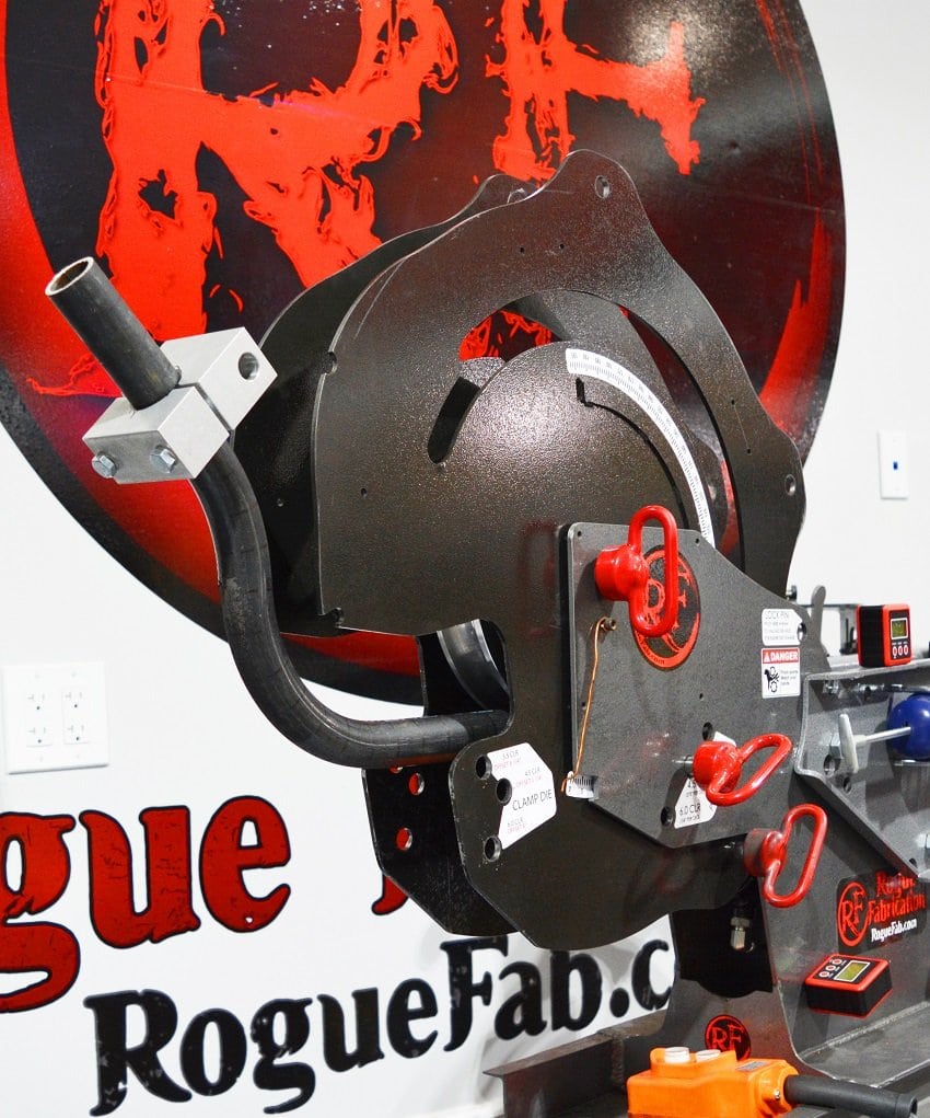
Method 1 puts the first bend inside the machine while you make the second bend. Method 2 is the opposite, it puts the first bend just past the bending die (but before the clamp) while bend 2 is formed. The benefits of this method are higher bend angles and affordable mandrel bender compatibility.
1. Make a bend like normal in your machine, and bend to 45 degrees.
2. Remove the clamp, move it right to the beginning of the bend from step 1. Clamp it tight. Now flip the clamp and material upside down (use our rotation gauges or a second clamp to get them perfectly coplanar if desired – link HERE opens in new window/tab). Your bend will be facing down out the front of the machine.
3. Advance the machine carefully until the pins are tight. Re-zero your degree indicator (unless you want to bend to “whatever many” degrees).
4. Bend to 45 degrees again. Remove the material. You will have a 45 degree S bend.
You can adjust clamp locations for the same angle and a greater offset distance. You can adjust bend angles as well.
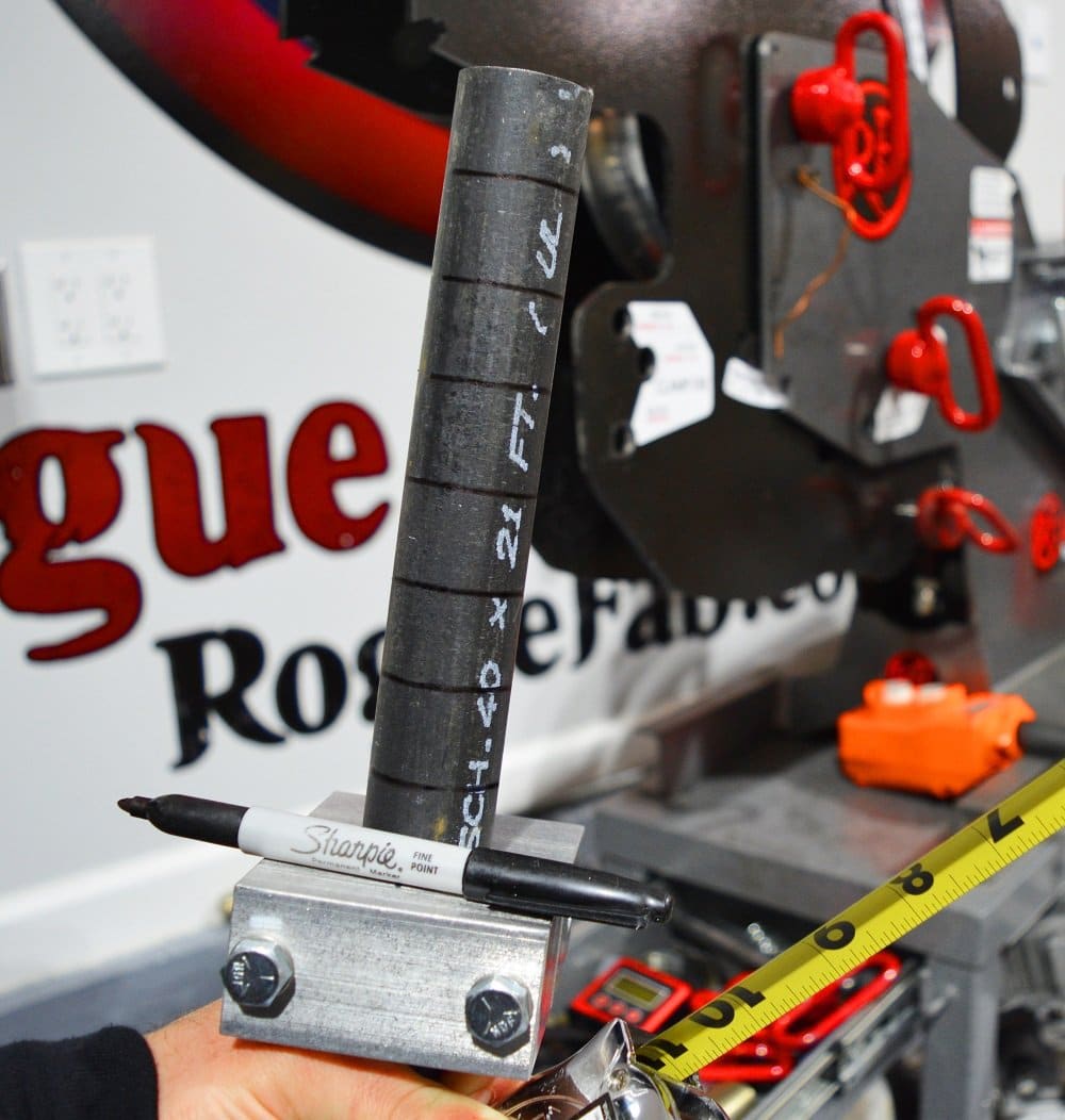
Tip – Draw rings on your tubing every inch with a sharpie before you start, and mark where you put clamp blocks while you’re experimenting. This is an easy way to measure where the clamps end up (count the rings and measure to the closest one) so you can replicate your work with precision.
Learn to Make Your Own Bend Recipies
Following our steps will only take you so far. Someday you will create something complex and want to make the same thing again – maybe even a mirror image of it.
Preparing for precise documentation of how to repeat a bending process is crazy simple. It only requires a sharpie, tape measure, and a plan.
Draw rings on your tubing every inch with a sharpie before you start. Our clamp blocks are great stencils for drawing these rings. Mark where you put clamp blocks for each bend while you’re experimenting. This is an easy way to measure where the clamps end up (count the rings and measure to the closest one) so you can replicate your work with precision. It is an excercise in futility to measure down a bent tube to a clamp to find out where to put that clamp on a straight piece to do it again. This puts “straight tube” measurements right through all the bends you can come up with. No more guessing at tube stretch. And no software required.
Bending 302
Enough with just making accurate bends where you want them. Do you want to know how to make bent tubing that most fabricators don’t even know is possible in a single piece? Let’s continue your learning. This is the next step on your path to success in fabrication.
How to Bend an OX COLLAR!
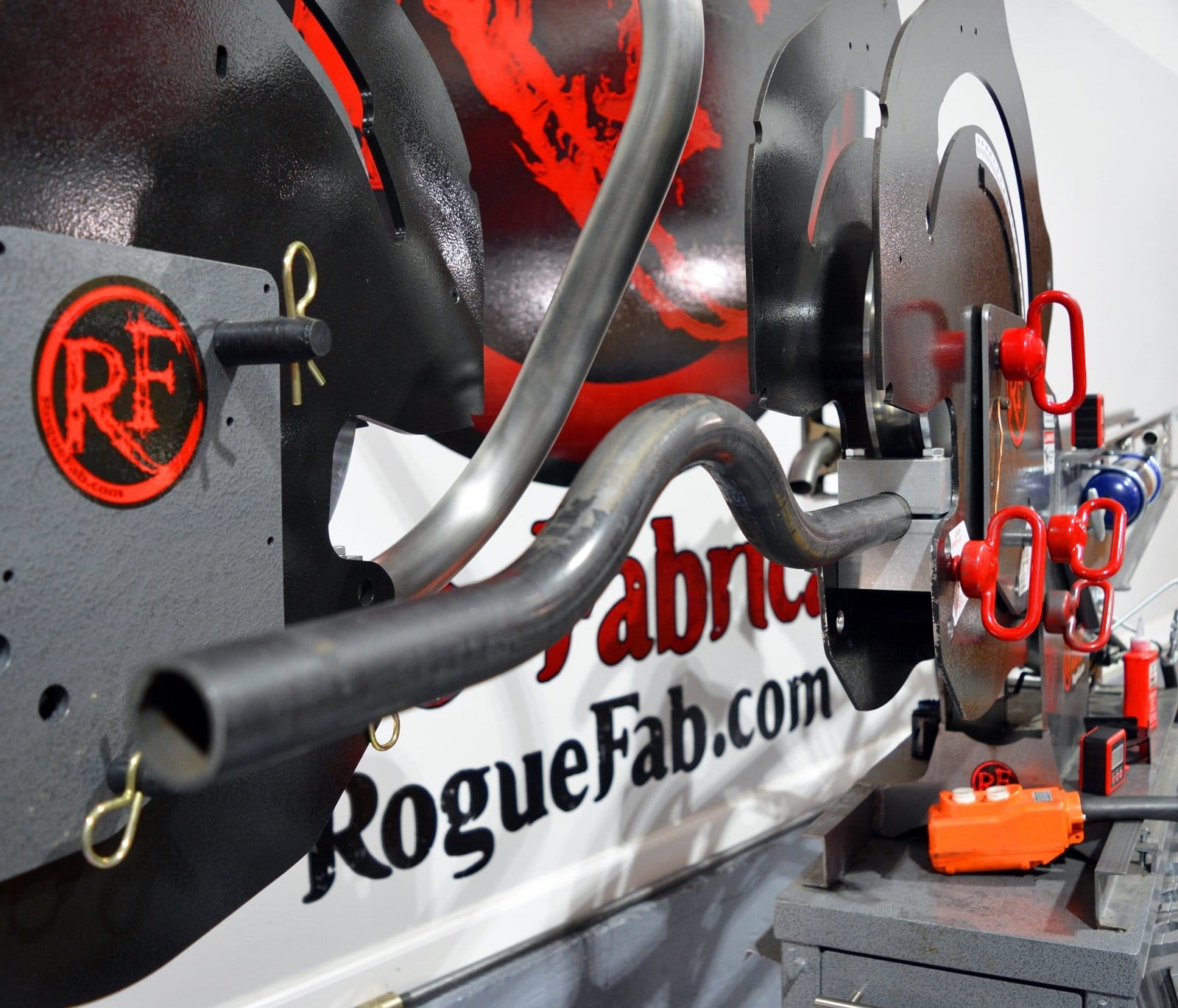
This is not for farming. Common applications for these are the rear floor of NHRA/SFI or other racing chassis and roll cages where the floor bar must be continuous but is allowed to be not-straight. Many regulatory bodies allow this, and it allows you to lower the whole floor of the car, allowing tall drivers to be comfortable. The driveshaft passes under (or over) the center offset.
THIS WAS DONE ON A 4.5 CLR DIE. THE NUMBERS WILL BE DIFFERENT FOR A 6.0 CLR.
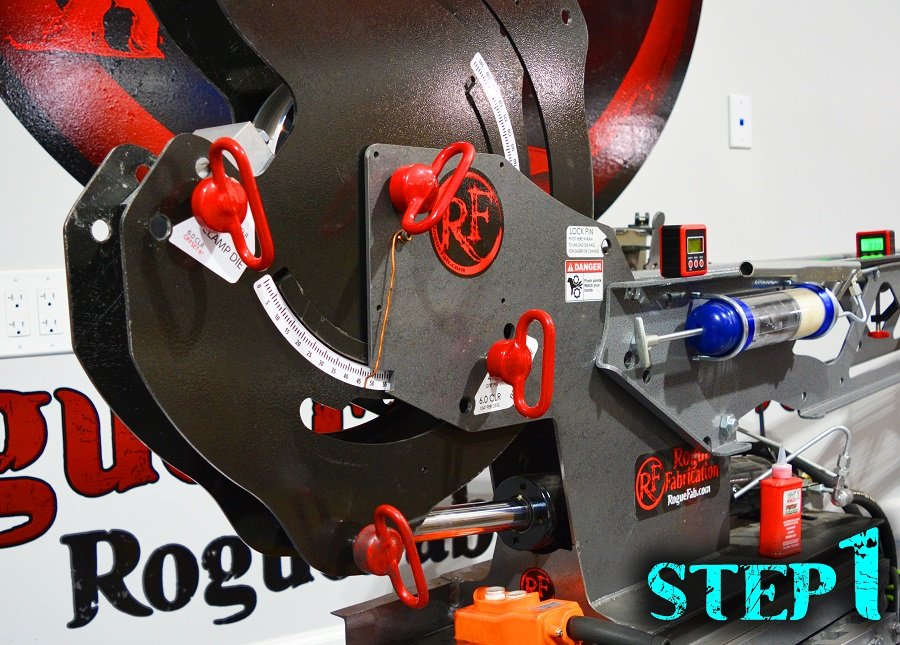
1. Make a bend like normal in your machine, and bend to 45 degrees. This bend is at 0 inches. (we put our clamp at the end of the tube).
TIP- Read all the steps and put the marks on your tubing NOW for all 3 clamp locations. They are much easier to measure on straight tube.
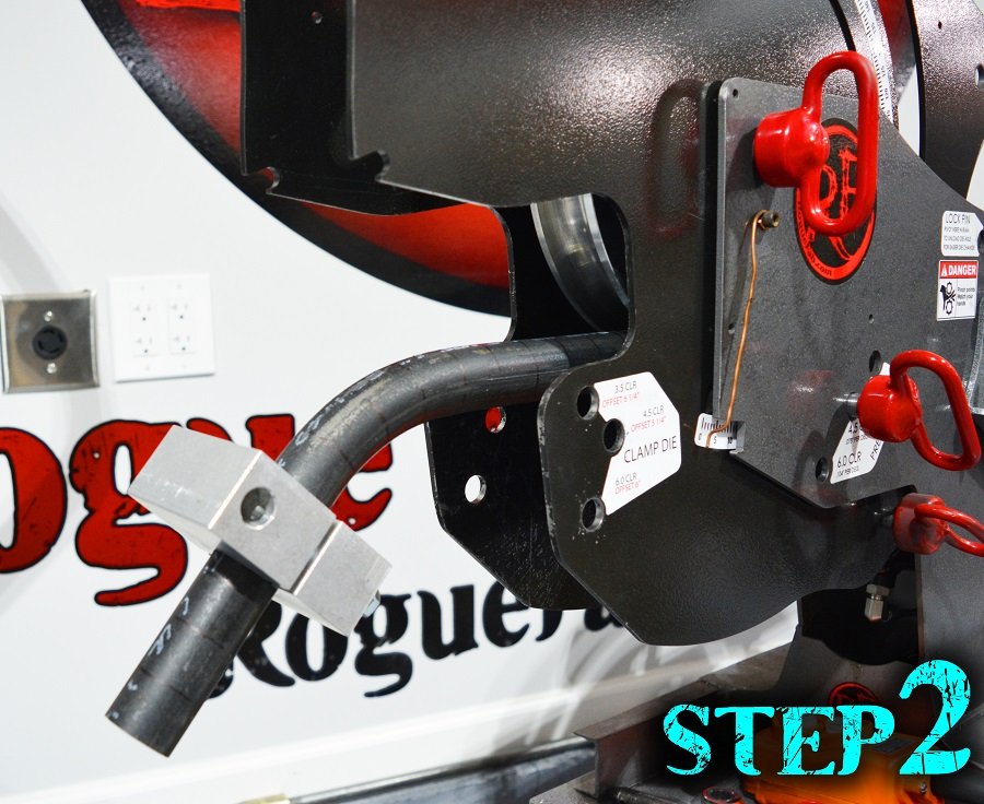
2. Remove the clamp, move it right to 3 3/8 inches from clamp location for bend 1. Clamp it tight.
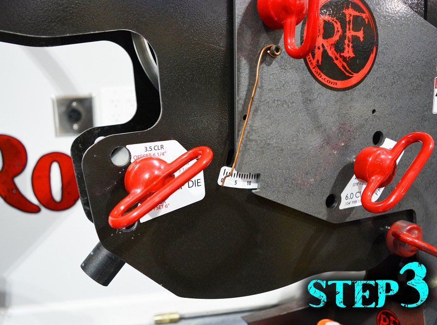
3. Now flip the clamp and material upside down -exactly 180 degrees. Re-zero your degree indicator. Don’t be a hack.
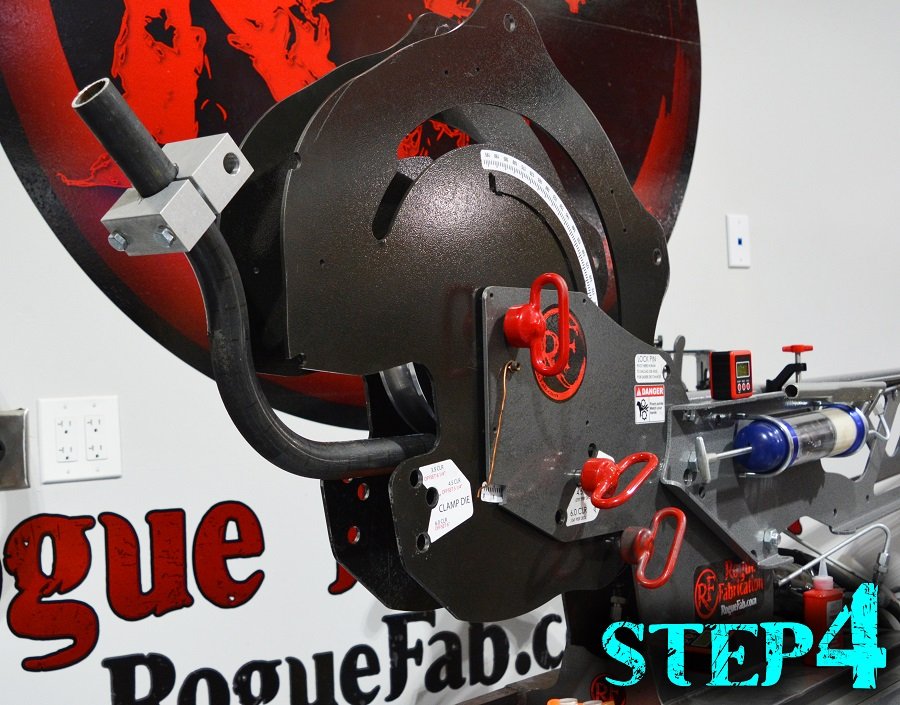
4. Bend to 90 degrees.
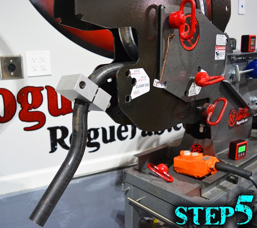
5. Remove the clamp, move it to 12 1/4 inches (from where you clamped in step 1, end of the tube in our case), and clamp it tight. This will be right in the middle of the 90 degree bend. We recommend you keep a clamp you abuse this way and at least one clamp you keep pristine, they’re super affordable HERE (link, new window/tab).
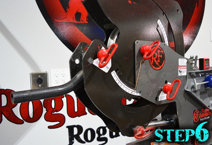
6. Flip again just like step 3, zero your indicator, and Bend to 45 degrees. Leave your clamp block on. Keep reading.
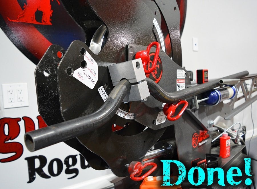
Getting it perfect (Angle) – make sure your material is not under bending force in the machine. Zero an angle cube left of all 3 bends. Check to the right of all 3 bends. If you’re under-bent by any amount, over-bend your step 6 bend by that amount (this is why you left the clamp block on!).
Getting it perfect (Offset) – Clamp your tube to a flat fabrication table. Is the other end hovering? If the beginning side is high, you need to add to the dimensions in steps 2 AND 6 equally. Expect about 3/4″ of offset correction for every inch you move these two bend locations. So if you’re “floor heights” are off by 1/4″, add 1/3″ to both offsets. If you have the opposite problem (lower before the set of bends), add with the same theory to ONLY the bend location in step 6.
You can adjust clamp locations for the same angle and a greater offset distance. You can adjust bend angles as well.
Tip – Draw rings on your tubing every inch with a sharpie before you start, and mark where you put clamp blocks while you’re experimenting. This is an easy way to measure where the clamps end up (count the rings and measure to the closest one) so you can replicate your work with precision.
Bending 303
We are 100% dedicated to your free education in metal fabrication and tube bending. While this section (303) teaches you nothing about bending, let it be our written commitment to you, our customer, that your success is our success. We will continue to develop the methods and teachings for helping you bend pipe, DOM tube, HREW tube, copper (hard and soft), titanium, inconel, Sandvik 2507 Duplex Stainless, architectural stainless, sanitary stainless, and Chromoly (as well as Docol R8). You are the star of this show, and we’re here to help you succeed. Come back later and we will have this section complete. Thank you very much for reading/watching.