Accuracy is everything when you’re bending tube, whether for roll cages, handrails, or custom chassis work. Most fabricators start with one of two methods: CAD software layout or hands-on prototyping tools like the Prototractor.
If you’ve relied on CAD to lay out your bends, it might be time to rethink your approach. In this post, we’ll break down the drawbacks of CAD and show why a physical layout tool like the Prototractor can save you time, reduce waste, and help you bend more accurately every time.
What is CAD Layout in Fabrication?
CAD (Computer-Aided Design) software allows fabricators to digitally plan their tube layouts, inputting bend radii, angles, and tube lengths into a drawing program to simulate the end result.
While CAD works in theory, in practice, it can lead to:
-
Extra time spent drawing and adjusting layouts
-
Errors from incorrect data or missed rotation angles
-
A disconnect between the design and real-world fit
-
Frustration for new students or team members with no CAD experience
What is a Prototractor?
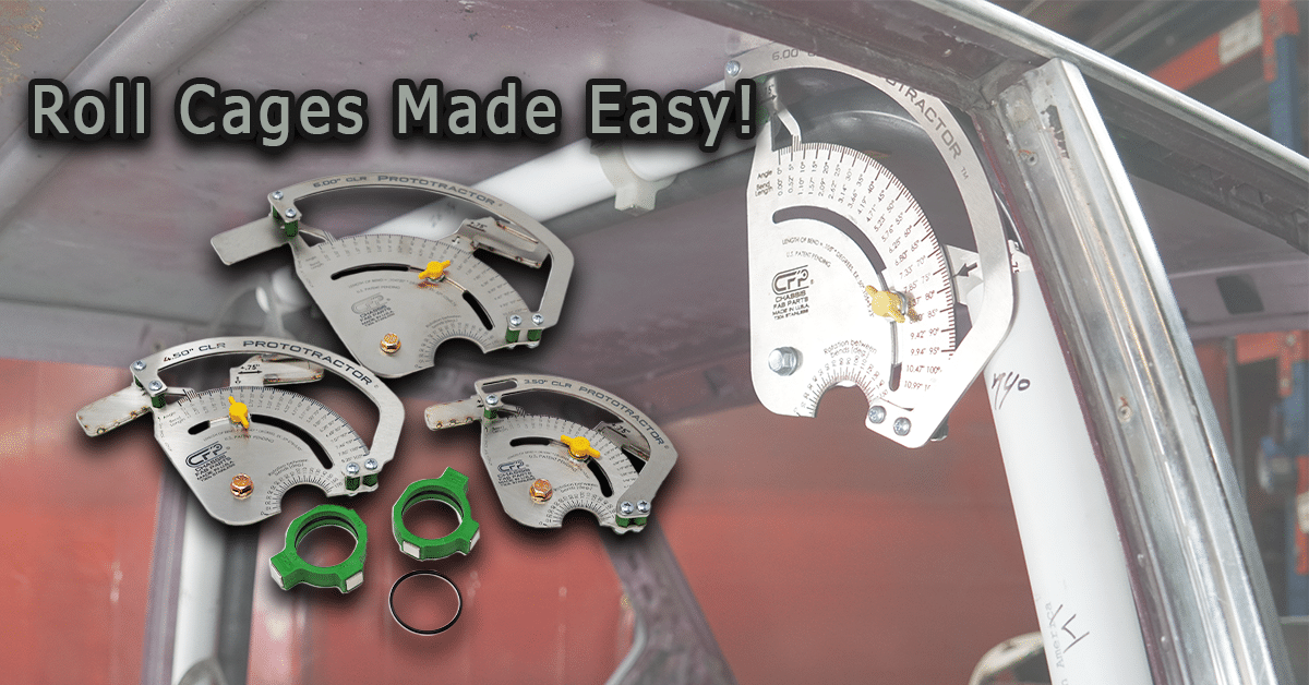
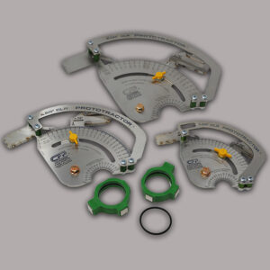
The Prototractor is a tool that allows fabricators to prototype full tube layouts using PVC pipe. Instead of laying out your bends on a screen, you use physical Prototractor components to simulate real bends and rotations, visually and in real-time.
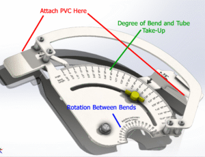
With the Prototractor, you can:
-
See bend angles and rotations clearly
-
Measure lengths between bends directly
-
Test and revise the layout before bending tubing
-
Train students or employees quickly and effectively
Learn more here: Prototractor Product Page
CAD vs Prototractor: Why Real-World Beats Virtual
While CAD software has long been the go-to for designing and planning tube layouts, it often falls short when it’s time to bring those designs to life. Creating a full tube layout in CAD can be time-consuming and difficult to visualize, especially for complex multi-plane bends. And even with careful planning, it’s still easy to end up with scrap due to misjudged rotation angles, bend locations, or overlooked real-world constraints.
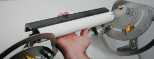
This is where the Prototractor offers a serious advantage. Instead of relying on a screen, fabricators can build a full-scale prototype using inexpensive PVC tubing and Prototractor jigs. You can measure angles and tube rotation directly from the mock-up, test your fit in real space, and make adjustments without wasting a single stick of steel. It’s faster, easier to teach, and far more intuitive, especially for hands-on learners.
Unlike CAD, which often requires a learning curve and access to expensive software, the Prototractor is ready to use right out of the box. It’s a perfect tool for shops that want to move fast and for schools training students who are still getting familiar with the tube layout. Plus, seeing a physical prototype helps eliminate guesswork and boosts confidence when it’s finally time to bend the real thing.
Want to see it in action? Watch the Prototractor Demo Video
Who Benefits from Using a Prototractor?
The Prototractor is designed for fabricators of all levels, whether you’re working in a professional shop or teaching a group of students in a classroom. For professionals, it’s especially useful for projects where precision and fitment are critical, such as roll cages, custom chassis, exhaust routing, and structural handrails. If you’ve ever had to redo a bend because a CAD layout didn’t quite translate to the real world, the Prototractor will quickly prove its value.
The benefits are just as strong in schools and training programs. The Prototractor gives students a tangible way to learn about bend-plane rotation, tube angles, and layout strategies without needing access to CAD software or making costly mistakes with steel. It’s an approachable tool that simplifies instruction and reinforces core fabrication concepts, making it ideal for high school welding classes, college-level fab programs, and even maker spaces or job training centers.
Final Thoughts – Ditch the CAD, Not Your Time or Materials
If you’ve been laying out your bends in CAD only to end up with fitment issues, extra trial bends, or scrap material, you’re not alone. CAD is powerful, but it’s not always practical for the shop floor.
The Prototractor gives you speed, confidence, and clarity. It’s a more innovative, hands-on approach to tube layout that works just as well for students learning the ropes as it does for pros on a tight deadline.
Ready to upgrade your layout process?
Explore the Prototractor system or contact our team to build a custom package that fits your needs.