How to Build a Roll Cage
Roll cages save lives when everything else has failed. Building one correctly takes the right materials, the right tools, and an understanding of what the structure is actually doing. This guide covers all of it: material selection, tube bending, notching, welding, floor mounting, weld access, and what tech inspectors are actually looking for. If you are building your first cage or your fifteenth, read it straight through. There is something here you will use.
What a Roll Cage Actually Is
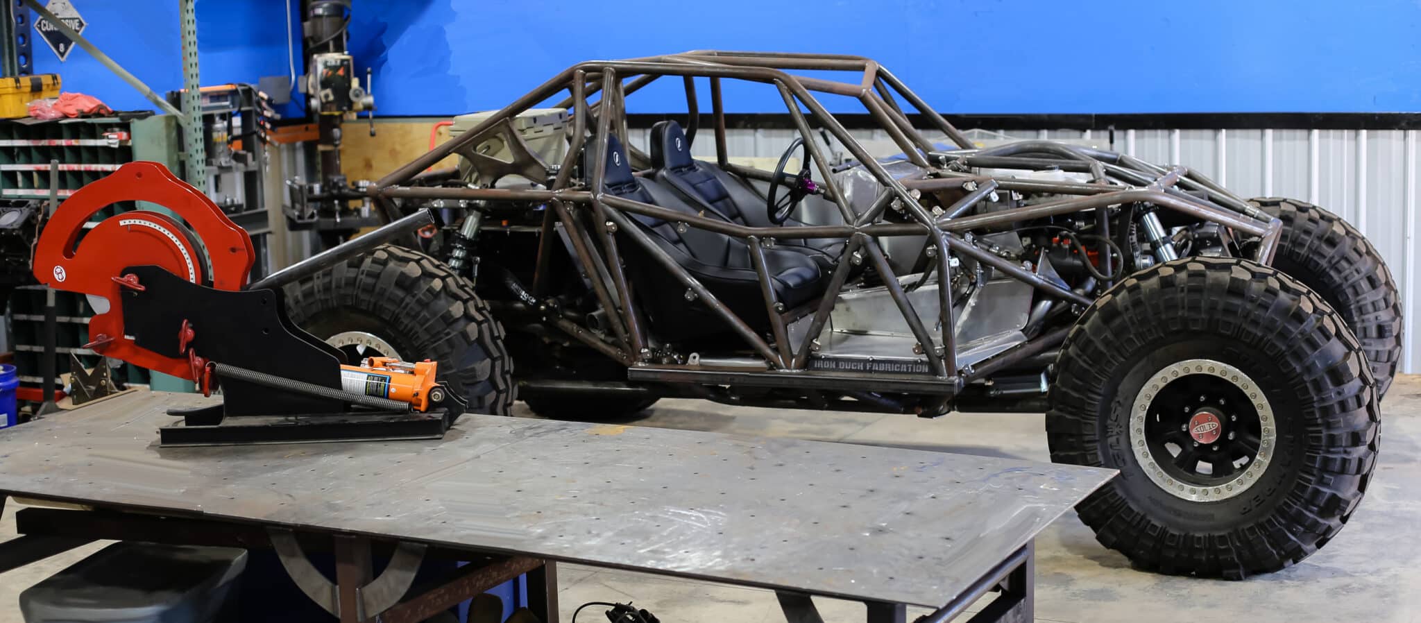
A roll cage is a welded tube structure built inside a vehicle to protect the driver in a rollover or collision. It works by creating a rigid survival cell around the driver that resists crush and maintains interior space when the rest of the car is deforming. Done right, it is one of the most effective safety structures in motorsport. Done wrong, it can be worse than nothing. A poorly fitted or poorly welded cage transfers energy directly to the driver instead of absorbing and distributing it.
A roll bar is not a roll cage. A roll bar is a single hoop behind the driver. It provides overhead protection in a simple rollover but does nothing for side impacts, front impacts, or complex rollovers where the car lands on a corner. If you are building something for actual use on a track or trail, build a cage.
Bolt-in kits exist. They are better than nothing for street cars in non-competitive use. For any sanctioned motorsport event, every organization we know of requires a welded cage. Bolt-in kits are mass-produced to fit a range of model years with a range of factory interior configurations. The fitment at the tightest end of that range is acceptable. The fitment at the loosest end has body-to-tube gaps that undermine safety, ergonomics, and appearance. We will talk about how to solve the fitment problem in the mockup section below.
Types of Roll Cages
By installation method
Bolt-in and welded-in. Bolt-in for street use or mild recreational applications. Welded-in for any sanctioned competition. Every major sanctioning body requires it.
By attachment point count
You will hear 4-point, 6-point, 8-point, and so on. The number refers to how many points the cage attaches to the vehicle structure. More points distribute load more widely and add more protection geometry. A 4-point cage provides overhead protection and basic rollover protection. An 8-point cage adds door bars, rear braces, and side intrusion protection. Your rulebook tells you what the minimum is. Build to that minimum at the very least, and understand why each element is there before you skip one.
By application
Circle track, road racing, rally, drag racing, off-road, sand cars, side-by-sides: each application has specific geometry requirements driven by crash modes specific to that sport. A circle track car takes most of its hits on the driver’s side. A rally car rolls. A desert race truck takes undercarriage hits and lateral loads from terrain. The cage geometry should reflect the real-world threat profile, not just meet the minimum bar count.
Material Selection
The structural integrity of a cage lives or dies in the tube material and the welds. Get these right and you can build a cage that will protect a driver in a serious incident. Get them wrong and you have a structure that looks like a cage but fails when it matters.
Check your rulebook first. Every sanctioning body publishes a materials list. Build to what is approved for your application. The notes below give you the technical background to understand why those materials made the list.
DOM 1020 / 1026: The Workhorse
Drawn Over Mandrel steel, 1020 or 1026 alloy, is what the majority of cage builders use. It is a medium-carbon steel with excellent weldability and excellent bending properties. Tensile strength minimum 85,000 PSI. Yield 77,000 PSI minimum. Tight dimensional tolerances from the DOM process make it consistent and predictable to work with. MIG or TIG welding are both broadly accepted with DOM. This is the material you should start with unless your rules require something else or you are building for peak-level competition where weight matters.
One clarification worth making: DOM and CDS (Cold Drawn Seamless) describe the manufacturing process, not the alloy. You will hear people use “DOM” as if it were a grade of steel. It is not. It is a process that produces tighter tolerances and better surface condition than ERW (Electric Resistance Welded) tube. DOM is the process. 1020 or 1026 is the alloy. When someone says “DOM tube for cage work,” they mean 1020 or 1026 alloy made by the DOM process. That is exactly what you want.
4130 Chromoly
Chromium-molybdenum alloy steel, stronger than DOM, lighter for the same wall thickness, and more demanding to weld. TIG welding is required in every sanctioned application. No exceptions. The reason is the heat-affected zone (HAZ): 4130 becomes brittle at and near the weld if not handled correctly, and the most likely failure point on a chromoly cage is right next to a welded joint. Most rulebooks require very tight pre-weld fitup gaps on chromoly joints, typically no wider than the diameter of your TIG filler rod. That means clean notching, tight fitup, and no shortcuts. If you have the welding skill and want the weight savings, 4130 is a legitimate choice. If you are still developing your TIG skills, start with DOM.
Docol R8
Dual-phase advanced high-strength steel engineered specifically for motorsport safety applications. 116,000 PSI tensile strength, roughly 10-15% stronger than 4130. Smaller heat-affected zone than 4130. Welds more like mild steel than chromoly despite the higher strength. Accepted by SFI and most major sanctioning bodies as a 4130 substitute. Growing adoption at the top level of motorsport.
There is genuine debate in the cage-building community about Docol R8 vs 4130. The material properties favor Docol by a clear margin. The counter-argument is that 4130 has a decades-long track record in motorsport that Docol does not yet have. Both are valid positions. We called the lead tech inspector for the 24 Hours of Lemons in 2023 and asked which material he would choose for a cage. His answer was Docol R8, and not by a small margin. That is one data point, but it is a data point from someone who inspects cages for a living.
T45 and 15CDV6
T45 is a carbon-manganese steel commonly used in FIA and stage rally applications. 15CDV6 is a chromium-molybdenum-vanadium alloy used in high-end European rally and circuit racing. Both are significantly stronger than mild steel, both are more expensive, and both require experienced TIG welding. If your competition requires either, your rulebook will say so. Most North American builders will never need to spec these materials.
What not to use
Aluminum: low yield strength, brittle at the weld, not approved by any sanctioning body we know of. Stainless: challenging to weld, requires back-purging, low yield strength in the common grades. Titanium: expensive, brittle, notoriously difficult to weld, not approved for cage use anywhere. Magnesium: flammable. Do not use magnesium for anything structural near a driver.
What about weight?
Steel alloys are dense. All of the materials above are close enough in density that the weight difference between a DOM cage and a 4130 cage of the same geometry is not the performance variable most people think it is. When your rules set a minimum tube diameter and wall thickness, every approved material will produce a cage in roughly the same weight range. Choose the material that fits your rules, your welding capability, and your budget, in that order.
Tube vs. Pipe: Use Tube
Tube and pipe are not the same. Tube is a structural member, sized by outside diameter and rated for strength. Pipe is a pressure vessel, sized by nominal inside diameter (which does not match the actual inside diameter), and rated to carry fluids. For any given nominal size, pipe is weaker, heavier, and less dimensionally consistent than structural tube.
Use tube. DOM steel tube. Not pipe. If someone tells you to build a cage from schedule 40 pipe because it is cheaper, they are steering you wrong.
There is a specific exception worth naming: ASTM A513 Grade B is a structural pipe with reasonable strength properties that you will see in recreational builds in the United States. It is not ideal and not approved for any sanctioned racing we are aware of, but it is far better than hardware store pipe. If budget forces the issue on a non-sanctioned project, A513 Grade B is the floor, not the default.
What Size Tube to Use
Your rulebook defines the minimum. Here are the most common specifications by application:
4×4, rock crawlers, buggies, exo cages, Jeeps
1.75″ x .120″ wall DOM is the most common choice. Use a 4.5″ CLR die for tighter clearances or a 6.0″ CLR die for cleaner bend geometry. The 6″ radius produces less deformation and looks better. If you are building an exo cage on a heavier vehicle, consider 2.0″ x .120″ for the primary structure.
Side-by-sides and SXS
Match the OD of the factory cage so bolt-on accessories (mirrors, belt mounts, lights) still fit. That is 1.75″ for nearly everything except the Can-Am Maverick, which is 2.0″. Use a 6.0″ CLR die. Secondary tubes commonly run 1.25″ OD on a 4.5″ CLR die.
NHRA / SFI drag racing
1.625″ x .083″ is the most common specification, but SFI 25.3 also requires 3/4″, 1″, 1-1/8″, 1-1/4″, and 1-1/2″ for various secondary members. Use a 6.0″ CLR for anything over 1.25″ OD, especially in thin wall material. Get the current SFI spec book. It is not free but it is not expensive, and you should own a copy rather than working from someone else’s printout.
SCCA / NASA road racing
1.625″ is most common, with some classes allowing 1.5″ and some requiring 1.75″ depending on car weight. Check the class-specific rules at scca.com and nasaproracing.com, both available for free. CLR guidance is the same as NHRA above.
SCORE and Ultra4 desert racing
SCORE has required 2.0″ x .120″ minimum for the primary cage structure on 4WD vehicles over 4,400 lbs for at least a decade. This puts you in M605 or M625 territory. Both handle 2″ tube. SCORE documentation technically requires mandrel-type bends. In practice, SCORE approves cages every year that are not mandrel bent, but that discrepancy is their problem to resolve, not yours. If your tech inspector asks, the M6xx mandrel attachment produces bends that satisfy the intent of any mandrel requirement.
Sand cars and dune buggies
No universal regulation. Scale to the vehicle: 1.5″ x .095″ for lighter and slower builds, 1.75″ x .095″ for heavier and faster. Recommended dies: 1.5″ OD x 6″ CLR primary, 1.25″ x 4.5″ CLR secondary, 1.0″ x 3.5″ CLR for small support tubes. Your life is on the line. Do not go light on the primary structure to save money.
JEEP Wrangler TJ / LJ / JK
Most builders use 1.75″ x .120″ wall. Your choice on 4.5″ or 6.0″ CLR die. The 6″ produces a cleaner bend and less deformation. The OEM cage on a TJ/LJ is 2.125″ OD. Jeep used the large diameter to compensate for minimal triangulation and a lot of unsupported bends in the factory design. Do not treat the OEM cage geometry as a reference for a replacement. It is a starting point to improve on, not replicate.
Hand railings
1-1/4″ schedule 40 pipe is the standard, 1.66″ OD, steel or stainless or aluminum. 4.5″ or 6.0″ CLR die. Meets most building codes at that size. Aluminum is acceptable here. Railings are not crash structures.
For a complete wall thickness capacity chart by tube OD and material, use our Bender Capacity Chart. All the data is there.
Tools You Need
You do not need to buy everything before you start. Here is what is required and what is optional:
Required
- Tube bender: A rotary draw bender with the right die for your tube OD and CLR. The M601 handles all cage work through 1.75″ tube and covers the majority of sanctioned builds. The M605 adds capacity to 2.0″ tube for SCORE and trophy truck work. Both share the same die ecosystem. If you start with an M601 and need more later, you upgrade the machine and keep all your dies.
- Tube notcher: Cuts the fishmouth profile at tube ends for tight-fitting weld joints. Not optional. A cage built with angle-ground notches will have gaps, and gaps weaken welds. Our VersaNotcher handles 5/8″ to 2-3/8″ OD. The UltraNotcher extends that to 3-5/8″ and adds a 270-degree angle range with a dual-pivot head.
- Welder: MIG for DOM. TIG for chromoly, Docol, and any sanctioned application that requires it. Both for shops doing varied work.
- Angle grinder: Cleanup and fit adjustment.
- Tape measure, angle finder, level, permanent marker.
- Cutting tool: Bandsaw, cold saw, or chop saw for cutting tube to length.
Strongly recommended
- Prototractors: Physical mockup tools that let you develop accurate tube layouts using PVC pipe inside the actual vehicle before you cut a single piece of real tube. A full set for a cage project runs around $500. On a cage build using chromoly at $100+ per stick, a single layout mistake can cost more than the Prototractors that would have prevented it. We use them in our own shop. See the Prototractor here.
- Bending software (Bend-Tech PRO or SE): Generates manufacturing instructions for every part: cut length, clamp location, bend angles with springback compensation, tube notching wrappers. Not required for simple work, but for a full cage with 20+ tube sections it pays for itself.
- Rotation gauges: Track tube rotation between bends. Critical for complex coplanar and non-coplanar bend sequences.
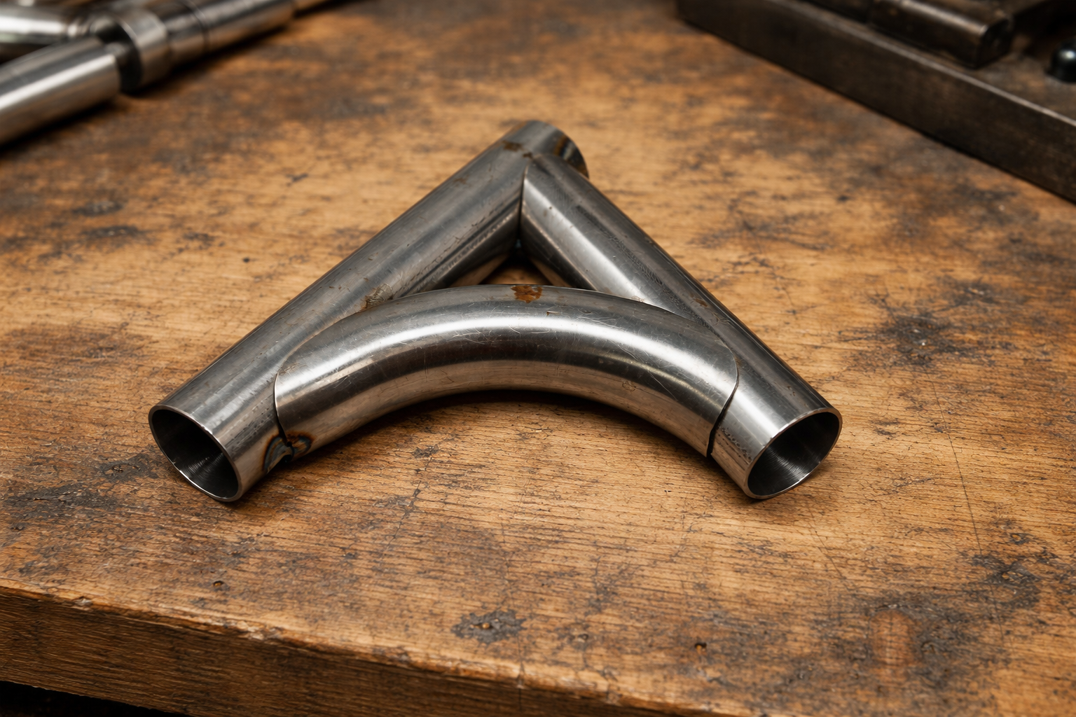
Bending the Tubes
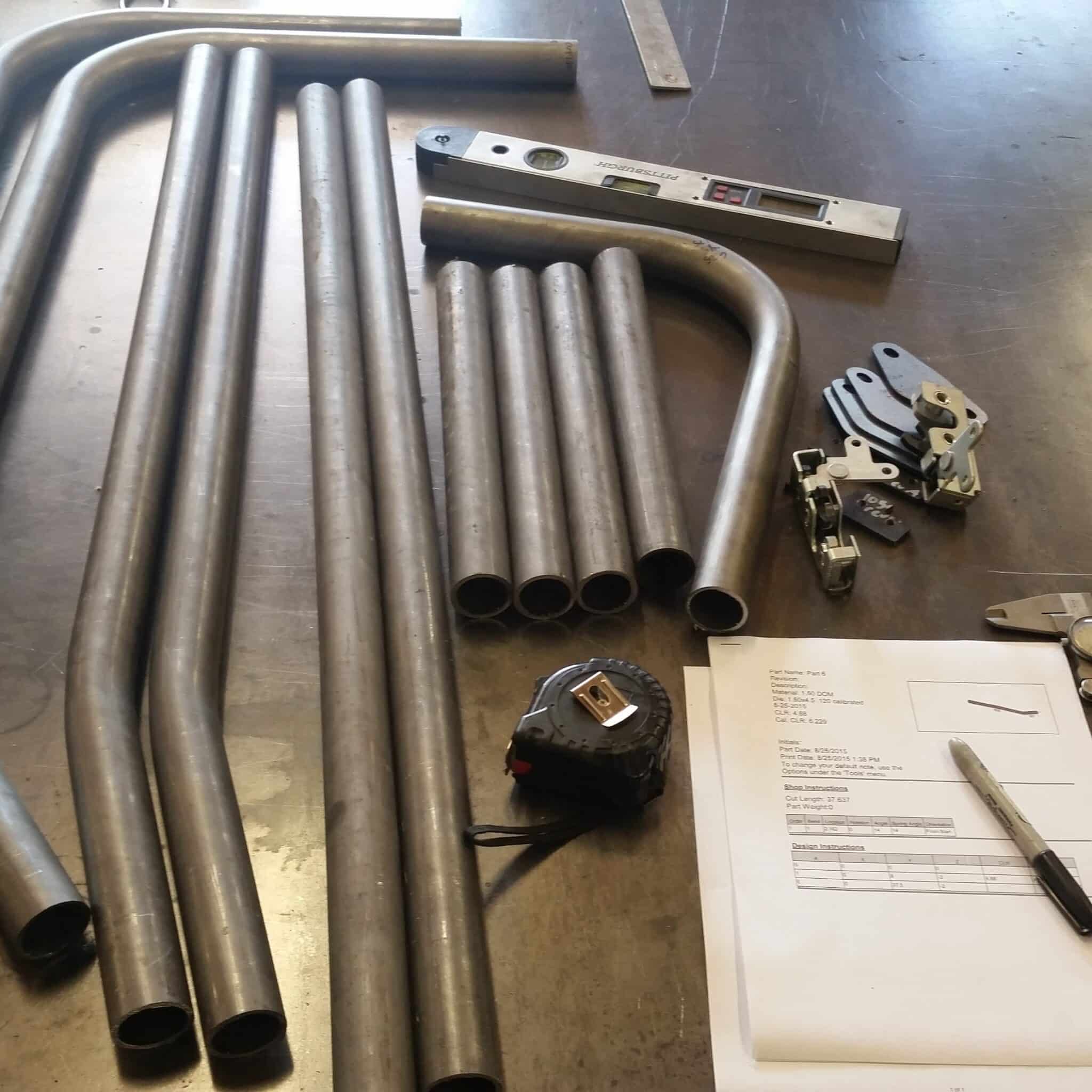
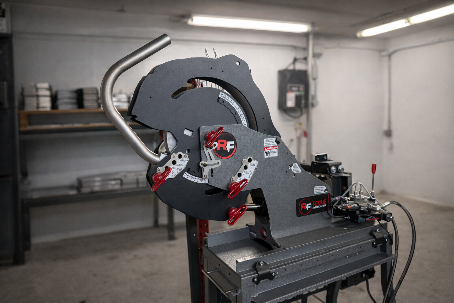
Rotary draw bending, which is what the M6xx does, clamps the tube at the tangent point and draws it around a fixed-radius die while a pressure die holds the back side of the bend from distorting. The result is a consistent, repeatable bend with defined geometry. This is the correct bender type for structural cage work. Ram benders and compression benders are for exhaust and plumbing pipe. They do not produce the dimensional consistency or bend quality that cage work requires.
Die selection for cage work
For most cage tube, use the largest CLR die that fits your geometry. A 6.0″ CLR die on 1.75″ tube produces a 3.43D bend, well above the 3.0D threshold where deformation starts getting serious. A 4.5″ CLR die on the same tube is a 2.57D bend and will produce more ovality and more wall thinning. Use the 6″ die unless the geometry forces you tighter. Your cage will look better and be stronger for it.
Lubrication
Use a bending lubricant. Bend All 002 is a good choice. Coconut oil works as a shop-floor substitute. Lubricant extends die life, reduces galling on the tube surface, and produces cleaner bends. On long production runs it makes a real difference. Get in the habit of using it on every bend.
Springback
Every material springs back after bending. The elastic portion of the deformation recovers when you release pressure. DOM 1020 springs back a predictable amount for a given radius and wall thickness. 4130 springs back more. Springback measurement is covered in detail on our Bending 101 page. The short version: zero your degree indicator with the machine loaded but not bending, bend to your target angle, back off pressure, re-snug the machine, read the actual angle, and calculate your overbend amount. Do this once per material per die and use that offset for every bend in the project.
Bend quality targets
Target 8% or less ovality at the bend midpoint. Measure with calipers: the difference between the widest and narrowest OD readings at the bend center, divided by the nominal OD. Above 10% and the section modulus loss starts to matter structurally. Most tech inspectors are not measuring ovality with calipers, but the physics does not care whether the inspector notices. Build to a higher standard than the minimum you can get away with.
To improve bend quality on thin-wall tube, add the Thin Wall Roller to your M6xx. It is a roller pressure die that installs in seconds and significantly reduces ovality on demanding wall ratio material. For the highest quality bends, roughly 1% deformation, the mandrel attachment is the answer. Shops that charge the most for cage work typically mandrel bend. Once you see a mandrel-bent tube next to a standard-bent tube from the same die, every other bend looks flat by comparison.
Our Bend Quality Calculator lets you calculate expected deformation for your specific tube size, wall thickness, and CLR before you bend. Use it when you are selecting dies for a new project.
Mockup Before You Bend
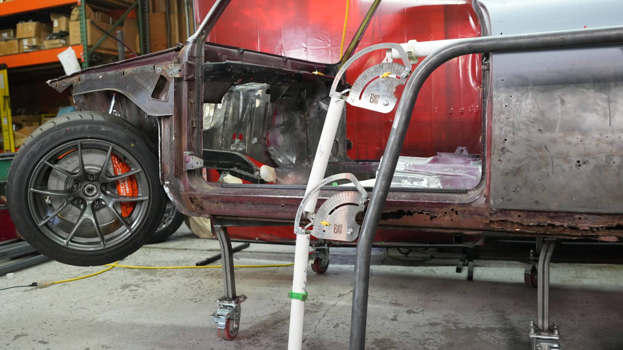
The single most common source of wasted tube on a cage build is layout error: bending a tube to the wrong angle or with the wrong rotation because the dimensions were measured off a sketch instead of the actual vehicle interior. Steel tube for cage work costs real money. Chromoly is over $100 a stick in most areas right now. One bad bend costs more than a set of Prototractors.
Prototractors are physical mockup tools that let you lay out tube runs using PVC pipe directly inside the vehicle. You develop the actual geometry, angles, rotations, and lengths, against the real structure, then transfer those measurements to the bender. No guessing. No scaling off drawings. The layout comes from the car.
This matters even more if you are starting from a kit cage. Mass-produced kits are designed to fit every car in a model line across multiple model years and factory build variations. The cage that fits your specific car may fit well or may have body-to-tube gaps that need to be closed. Prototractors solve the fitment problem whether you start from a kit or from scratch. Prototractors start at $87 for the smallest size and scale up from there. A full set for a roll cage project runs around $500.
Notching and Fitup
Every tube junction in a cage is a welded joint. The strength of that joint depends almost entirely on two things: fitup and weld quality. Fitup comes first.
A tube notcher cuts the fishmouth profile at the end of a tube that allows it to seat against a round tube with full contact around the perimeter. A well-notched joint has zero gap or a gap measured in thousandths of an inch. A poor joint, whether angle-ground, hand-cut, or cut on a dull notcher, has gaps you can see from across the shop. Those gaps are structural defects before you ever strike an arc.
For chromoly and Docol cage work in sanctioned motorsport, most rulebooks define the maximum allowable pre-weld gap as the diameter of the TIG filler rod used to weld the joint. A 3/32″ TIG rod means your maximum gap anywhere in the joint is 3/32″. That is tight. It requires a sharp hole saw, a properly set-up notcher, and careful work. It is achievable on a VersaNotcher or UltraNotcher with the right setup. It is not achievable on a cheap imported notcher with cast aluminum components.
For joints that intersect at compound angles, like a tube meeting a main hoop at a non-perpendicular angle, a notching system with compound angle capability is essential. The VersaNotcher adjusts to 225 degrees. The UltraNotcher goes to 270 degrees with a dual-pivot cutting head and can notch tubes on a bend.
Bad fitment in the vehicle is the second-most-common failure mode in cage building. Large body-to-tube gaps, mismatched angles between tubes and panels, and asymmetry in the cage geometry all happen when builders skip the mockup step and transfer dimensions from a drawing instead of the car. An expensive cage built by a name shop does not guarantee a well-built cage. The fitment quality shows before the welder picks up the torch.
Welding
Follow your rulebook first. The notes below are background for understanding why the rules say what they say.
MIG vs. TIG
MIG welding is faster, more forgiving of fitup gaps, and easier to learn. TIG welding is slower, more precise, and produces cleaner welds with less heat input and a smaller heat-affected zone. Both produce structurally sound welds on DOM mild steel when done by a competent welder. Most rulebooks allow MIG on mild steel cage structures.
For chromoly: TIG only, in every sanctioned application we are aware of. The reason is the HAZ: MIG on chromoly produces a wider, hotter heat-affected zone that increases the brittleness problem at the weld. TIG keeps the HAZ narrow and allows better heat control. The SFI and NHRA both require TIG on 4130 chromoly cages. Docol R8, despite being a more advanced material than 4130, follows mild steel welding rules in most sanctioning bodies. MIG is generally accepted. Check your specific rulebook.
Fitup first
Poor joint fitup is the most common reason cages get built wrong. A welder covering a large gap with multiple passes is not filling the gap with weld metal of the same properties as the base metal. They are building up a shaped deposit that has shrinkage stress, possible porosity, and reduced ductility. Weld over a good joint once. Do not weld over a bad joint twice.
Full penetration
Welds must fully penetrate the joint. A weld bead sitting on top of the tube surface is decoration, not a structural joint. Use the correct filler rod, the correct heat input for the material and thickness, and the correct travel speed. If you are new to TIG welding tube joints, practice on scrap first. Cut your test welds in half and look at the cross-section. That is how you know if you are penetrating.
Do not grind structural welds
Grinding a cage weld to make it look cleaner removes material from the weld profile and introduces stress risers. Tech inspectors are not looking for cosmetically perfect welds. They are looking for undercut, cracks, incomplete fusion, and non-compliant dimensions. Do not chase the Instagram dime-stack look on structural welds. Weld correctly, leave the weld alone, and move on.
Stacking tacks
Every start and stop in a MIG or TIG weld is a potential defect, a point of incomplete fusion or trapped porosity. Stacking tacks is not structural welding. Weld each joint in as few passes as the geometry allows. Practice on tube scrap until you can run a consistent pass around a fishmouth joint without stopping. Then weld your cage.
Weld Access to the Top of the Cage
This is one of the most overlooked topics in cage-building guides. Getting full-penetration welds on the top nodes of a cage, specifically the joints at the top of the main hoop and at the top corners of the A-pillar and B-pillar connections, is physically difficult or impossible once the cage is installed in the car. If you tack the cage together inside the car and try to weld the top joints by reaching up through the interior, you are not going to get good welds. You are going to get the best welds you can manage in a difficult position, which is not the same thing.
There are three methods that give you proper access to the top joints. Choose based on your build type and your rulebook.
Method 1: Drop Through the Floor (most common in road racing and circle track)
Drill holes in the floor at the cage leg contact points. Lower the fully assembled cage through the floor. Now all the top joints are accessible from above with full range of motion. Weld every top joint completely. Lift the cage back into the car and install floor plates over the holes. The floor plates become part of the proper floor mounting. They are structural, not just patch panels. This is the most common method in road racing and circle track. It adds one step but produces reliably better welds at the most critical joints in the structure.
Method 2: Plinth Boxes
Build the cage legs short so the ends sit above the floor with enough of a gap to elevate the entire cage structure off the floor. Tack everything together with the cage elevated. Weld all the top joints completely while the cage is sitting up with good access. Then fabricate steel box sections (plinth boxes, also called mounting boxes or boxing plates) that fill the gap between the leg ends and the floor. The cage legs weld to the top of the plinth boxes. The boxes weld to the floor or body structure. This method avoids cutting holes in the floor entirely, adds structural mass at the mounting points, and gives you clean top-joint welds. It is more work to fabricate the boxes, but some builders prefer it for unibody cars where floor cutting is undesirable.
Method 3: Cut the Roof (not recommended for most builds)
Some dedicated circle track builds cut the roof off the car to get unrestricted access to the top joints, then reinstall the roof. This gives you the best possible weld access but permanently compromises the OE roof structure, creates rust traps at the seams, and is not appropriate for any build that started as a street car or unibody. If you are building a dedicated spec racer from a bare shell that will never see the street again, it is an option. Otherwise, use Method 1 or 2.
Never tack the top joints and leave them tacked. A tacked-only joint is not a structural joint. A cage with tacked top nodes is not a cage. It is a liability. This is the mistake that turns a cage into a projectile instead of a survival cell. Weld every joint completely or do not call it a cage.
Floor Mounting: Not Optional
Every cage leg must terminate at a proper attachment point in the vehicle structure. This is not optional and it is not a detail. A cage that is not properly floor-mounted will shear away from the car in a serious incident and provide essentially zero protection. The failure mode is the cage moving independently of the car and striking the driver directly.
Common approved methods, check your rulebook for what is required in your application:
- Welded floor plates: Plate steel welded to the floor. Cage tube welds 360 degrees to the plate. The standard method when using the drop-through-floor approach. 3mm plate minimum for most applications, thicker for heavier builds.
- Plinth boxes: As described in the weld access section. Spreads load over a larger area and adds structural depth at the mounting point. More work to fabricate but a structurally excellent solution.
- Sandwich plates: Plate steel on top of the floor, plate below, bolted through with rated hardware. Required in some bolt-in configurations and allowed in some welded configurations. Distributes load through the floor panel rather than concentrating it at a weld.
- Frame tie-ins: Some applications require tying the cage directly to the vehicle frame rail rather than just the floor. Always preferred when the rules allow and the structure supports it. Do not weld to frame rails in a way that eliminates body mounts without understanding what that does to chassis geometry and crash behavior.
The floor or body structure under every mounting point must be solid. If there is surface rust, scale it back and assess the metal thickness. If the floor is thin or compromised, plate it from underneath first with fresh steel. A cage welded to a rotted floor is not attached to the car. It is attached to material that will tear in the first serious load event.
Cage Design Principles
Cage geometry is not arbitrary. Every design choice either adds or subtracts from the structure’s ability to resist a specific load. Understanding the principles behind cage design helps you evaluate a design you are working from, identify weak points, and make intelligent decisions when the geometry of the vehicle forces you to deviate from the textbook.
Triangles, not squares
Triangles are the fundamental structural unit of a cage. A square frame section under load will parallelogram. The joints rotate and the structure deforms. A triangle cannot change shape without changing the length of one of its members. Every rectangular or trapezoidal panel in a cage needs a diagonal member to split it into triangles. Door bars, X-members, kicker bars, and rear diagonals all serve this function. If you can identify a four-sided panel in your cage without a diagonal, that is a structural weak point.
Avoid T-junctions
A T-junction is a tube meeting another tube perpendicularly at a point that is not a node, not supported from the other side. Under load, the unsupported tube wall at the junction deflects before the joint fails, reducing effective weld area and concentrating stress. Wherever a cage member terminates into the side of another member, look for a way to gusset it or relocate the junction to a node. Some T-junctions are unavoidable. Minimize them.
Keep body-to-tube gaps tight
The closer the cage tubes sit to the interior roof, pillars, and doors, the less distance a driver’s head or body can travel before contacting hard structure in a crash. Tight body gaps require accurate mockup work. That is where Prototractors earn their keep. A kit cage with 3-inch body gaps because the manufacturer designed for the loosest-fitting model year combination in the lineup is providing less protection than it appears to.
Down bar angle
Front down bars, the tubes that run from the top corners of the main hoop forward to the floor, should not have an excessive lean angle. A down bar that is nearly horizontal provides far less load path efficiency than one that runs at a steeper angle. Add a tube between the down bars if the geometry allows. It reduces the unsupported length of each bar and stiffens the front of the cage significantly.
Kicker bars
Kicker bars run from the top of the rear hoop rearward and down to the vehicle structure. They resist rearward load on the main hoop and stiffen the connection between the cage and the rear of the car. Any cage that sees serious rollover risk should have them. Check your rulebook. Most organizations require them for the competition levels where real rollovers happen.
Unsupported member length and the tube calculator
The load capacity of a tube in compression drops dramatically as unsupported length increases. A 44-inch door bar carries a fraction of the load that a 44-inch bar gusseted at 10 inches from each end would carry. The gussets drop the longest unsupported span from 44 inches to 24 inches, and the strength difference is significant.
Our tube calculator is a material comparison and effective member length tool, not a cage design tool. It does not model the full structure. What it does is let you compare materials and calculate what a change in unsupported length does to the stress capacity of a given tube under a given load. Walk a real problem through it: enter your door bar dimensions, change the material from DOM to Docol, change the unsupported length by adding intermediate nodes, and see what the numbers tell you. The calculator is behind an email signup, free to use, and the data it outputs comes from real structural engineering, not spec sheets.
Gussets
Gussets reduce stress concentration at joints and reduce unsupported member length. They add weight and complexity. Use them where the geometry creates a vulnerable joint or an overly long unsupported span. Do not over-gusset a cage trying to make it bulletproof on paper. Excessive gussets add weight high in the vehicle, raise the center of gravity, and can stiffen the structure past the point where it absorbs energy through deformation. A properly triangulated cage does not need a gusset on every joint.
Padding
High-density foam padding on tubes in the driver’s strike zone is required by most rulebooks and is always a good idea regardless. Padding does not make the cage structural. It reduces the severity of contact between the driver and hard tube in a crash. Use SFI-rated or FIA-rated padding in any sanctioned application. Generic foam is not a substitute.
Bend Quality
Bend quality in cage work is not scrutinized as aggressively as material selection or bar placement, but it matters. A bend with 15% ovality has measurably reduced section modulus compared to a straight tube of the same material. That reduction is real whether or not anyone is measuring it at tech inspection.
Target 8% or less ovality. Measure at the midpoint of the bend with calipers: widest OD minus narrowest OD, divided by nominal OD. If you are over 10%, look at your die selection and bending technique before you weld that tube into a cage.
The easiest ways to improve bend quality: use the largest CLR die the geometry allows, use bending lubricant, and add the Thin Wall Roller pressure die if you are working with wall ratios above 14. For the best possible bends, the mandrel attachment reduces deformation to roughly 1% in the right application. Not required for most cage work, but if you are building at a level where the quality of the work matters, it is worth considering.
Tech inspectors are checking tube dimensions, material markings, weld quality, and compliance with the design spec. They are not typically measuring bend ovality with calipers. But the fabricators who are most respected in this industry hold themselves to a standard above what the inspector requires. The inspector’s threshold is the floor, not the goal.
Chassis Rigidity and Center of Gravity
A properly designed and installed cage stiffens the chassis, a genuine performance benefit in road racing and off-road applications. A stiffer chassis gives the suspension a consistent platform to work from. Damper settings, alignment angles, and spring rates are all calibrated against a chassis that behaves predictably. A flexible chassis absorbs energy that should be going to the tires and changes geometry under load in ways that make the car inconsistent. A cage fixes that.
The tradeoff is weight up high. Every tube in the cage adds mass above the vehicle’s center of gravity, raising it. This is real and worth knowing. In a road racing application on a car with low roll center geometry, it matters. In an off-road application where you are adding protection against a real rollover risk, the safety benefit of the cage far outweighs the CG penalty. In most applications, the chassis stiffness gain is at least as significant as the CG penalty, and the safety case is not even close. The cage wins. Build the cage, dial the suspension to account for the added unsprung weight and raised CG, and move on.
Tech Inspection
Tech inspectors are checking for specific failure modes, not auditing the aesthetics of your welds. Understanding what they are actually looking for helps you build to the right standard.
What gets cages failed at tech:
- Non-compliant tube dimensions: Wrong OD, wrong wall thickness, or no visible material markings on the tube. Mark your tube before you cut it. Take a photo. Have the material cert if your event requires it.
- Undercut welds: Where the weld bead meets the base metal, if there is a groove or notch cut into the tube wall, the inspector will see it. Undercut reduces the effective weld throat and is a sign of too much heat or too fast a travel speed.
- Dented or kinked structural tubes: Any deformation visible on a structural tube is a rejection. This includes tubes damaged during installation. A pipe wrench mark on a cage tube is enough to raise questions.
- Tacked-only joints: Joints that were never fully welded. This gets cages rejected and for good reason.
- Non-compliant design: Missing members, incorrect angles, wrong attachment geometry. This is why you read the rulebook before you start, not after.
Hold yourself to a higher standard than the minimum. Build the cage that you would want around you in the worst-case scenario, then build it that way for your customer too.
Regulatory Bodies and Rulebooks
Your cage must meet the specific requirements of the organization overseeing the event or series you are building for. Generic guidelines, including the ones in this article, are background knowledge, not a substitute for the actual rulebook. Read your rulebook before you start building.
- NHRA: The NHRA handbook covers cars running 8.50 second ET and slower in the 1/4 mile. It is available free from NHRA online. Faster cars are governed by SFI.
- SFI Foundation: SFI spec books are not free. They cost a small amount and you should buy your own copy. Do not work from someone else’s printout or a scanned copy from a forum. The spec you are building to needs to be the current version and it needs to be yours. sfifoundation.com
- SCCA: Class-specific rules available at scca.com. Free for most classes.
- NASA (National Auto Sport Association): Available at nasaproracing.com. Free.
- SCORE International: Trophy truck and desert racing specifications. See the SCORE website for current documentation.
- Ultra4: King of the Hammers technical regulations. Check the Ultra4 Racing website for current requirements.
- FIA: European and international circuit racing and rally. FIA homologation documents are available through the FIA Technical Department for applicable classes.
If you are building for a local event, track day series, or club race, contact the organizer directly and ask for the cage specification they enforce. Some local events enforce national standards by reference. Some have their own. Know before you build.
What It Costs to Build a Roll Cage
The tools are the primary cost. The tube is secondary. Here is a realistic breakdown for a first build:
Tools (one-time cost)
- Tube bender (M601 with one die, hydraulics): around $1,500 shipped and ready to bend
- Tube notcher (VersaNotcher): $570
- Welder (MIG suitable for DOM): $700–$1,200 depending on brand and amperage
- Prototractors (full set for a cage project): around $500
- Angle grinder, tape measure, level, marker: $100–$150 if you do not already own them
Tool investment for a first cage: $2,800–$3,300 if you are starting from nothing. Every cage you build after the first one amortizes that cost further.
Materials per cage
- Tube (6 sticks at 20 feet for a basic 8-point cage): $400–$700 depending on material and current steel prices. One spare stick is not optional. Have it before you start.
- Floor plates, gusset material, mounting hardware: $100–$200
- Welding wire and shielding gas: $50–$100
Material cost per cage: $600–$1,000. Less than the tools, which surprises most first-time builders.
A professional shop doing the same work will charge $2,000–$6,000 or more depending on complexity, material, and their labor rate. Building your own cage with the right tools produces a result that is structurally comparable to professional work and gives you the hands-on knowledge to maintain and repair the cage over the life of the vehicle. The tools also stay with you for every project after this one.
The Right Bender for Your Cage Build
The M601 handles the full range of cage tube through 1.75″ OD, which covers the majority of sanctioned cage builds. The M605 adds 2.0″ capacity for SCORE and trophy truck work. Both machines share the same die ecosystem: over 50 die sizes, the same cart, the same hydraulic options, the same mandrel attachment. Start with an M601 and if the work grows, the upgrade path does not require replacing what you already own.
Every M6xx ships from Sandy, Oregon ready to bend. The frame meets the FTC standard for domestic manufacturing. The hydraulic options include imported cylinders, which is why we do not put an unqualified Made in USA claim on the complete machine. That is the honest answer. What we can say without qualification: these machines are designed and built here, by people who bend tube for a living, and they are backed by technical support that no other bender manufacturer in this market provides.
M605 Tube Bender, up to 2″ tube
M625 Tube Bender, extreme heavy duty
Mandrel Bender Packages
Prototractors from $87
Questions about die selection, machine capacity for your specific tube and wall thickness, or what a rulebook requires for your application: call us at 503-389-5413 or email [email protected]. We answer the phone.
[…] also bends aluminum and super thick DOM tubing sizes and bends 4130 Chromoly steel tubing easily to build roll cages that will pass technical inspection[…]